• The move to the new server is done. There are some software and database maintenance updates in process. This has us passing the hat around to help out. We appreciate any donations. Seriously, even a dollar helps. The payment page may be found here - https://www.audiokarma.org/support.html

Fisher 800c project for 2014

Nice cabinet Don. There's enough room in there for EH's if it should comes to it. Jim McShane has the TUNG-SOL Re-Issue's now. About $125 a quad. And he said that they have been testing out really good on his test rig. Reports from the "peanut gallery are positve too from what i've read. I'm seriously considering a quad, now.

What are those GINORMUS speakers behind it. Might make for a good match.
 
Those are EV-Six speakers

4 way with 18" woofers

I recapped them with Dayton caps

They FILL the room in many ways
 
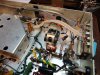
I can't find R128 and R123

Could someone please help me locate these resistors

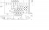
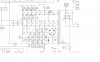
I found them on the schematic but I cannot find them on the board

R128 is a 1.2k resistor
R123 is a 1.2k resistor

One of them is a 5 watt, the other a 2 watt

attachment.php


attachment.php
 

Attachments

  • DSC03454.jpg
    DSC03454.jpg
    124.4 KB · Views: 138
  • Untitled.jpg
    Untitled.jpg
    37.6 KB · Views: 125
Last edited:
In the original build, these two resistors are located over in the power amplifier area. R128 is a long usually green, but sometimes clay red cylindrical resistor that is unmistakably obvious, while R123 is the typical color coded resistor (brown-red-red, silver) that is located close to R128, but further down in the chassis. In the original build, R123 is a 1 watt resistor.

I hope this helps!

Dave
 
Looking in the wrong area

Thanks Dave

It is hard to associate these two resistors with the schematic

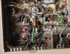
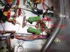
Must be these two. The long green one and the 1 watt Brown/Red/Red next to it
attachment.php
 

Attachments

  • R128 r123.jpg
    R128 r123.jpg
    120.4 KB · Views: 132
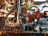
R128 is the BIG Green or reddish brown 1.2K 7W resistor in the middle of the output's and is tied to the screens (pin 4 on V11 or 13).

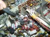
R123 is a 1w BRN-RED-RED between C87D and C87C. Both the 800-C I took these pictures from (43355c) and my Executive (10483) both have R123 on the can as original. This is in contrast to Dave's location. I'd say look in both. locations.


In the two pics the 1st pic shows R128 mine is now a 10W Brown ohmite. The 2nd shows E123 at the point of the screwdriver.

attachment.php


attachment.php

Larry
 

Attachments

  • 100_4696.jpg
    100_4696.jpg
    171 KB · Views: 145
  • 100_4698.jpg
    100_4698.jpg
    142.4 KB · Views: 142
Larry - Mine does not look like that

I have the three resistors (100k R115 and 22k R117 and 2.7k R120) but the one you are referencing is not in the original build at that location. Yours shows four resistors on that can, mine has three

The only one watt Brn/Red/Red is next to the BIG 1.2k green one

Whatta ya think guys
 
Last edited:
Your right R123,120,117 and 115 going to ground. Maybe they changed the setup. With R123, If it's right next to R128 check and see if one end wires to C87D(it may be on the same terminal as R128) and the other end to the center tap lead for the primary side of the output transformers. If so that's it.
 
Last edited:
One of these days we;re gonna have to sift thru all these threads and make a list of changes just to confuse and confound future techs. Imagine a boatload of white haired 21 year old techs with very little up top!!!!
 
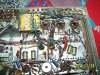
Okay, I got the rectifier done, the bias caps installed. diodes, the .01 1600's and the .1 630v
attachment.php


And now these two resistors

next is the big can swap out

I'm trying to document each step of the McShane kit install
 

Attachments

  • DSC03453.jpg
    DSC03453.jpg
    106.8 KB · Views: 74
Last edited:
You're doing great! I'm sure you will be well rewarded from your work, and quite pleased with your Fisher!

Dave
 
You've got it on the run, Don. Doing great.

Changed out my Romex buss bar for the screens and ran it like Dave described in his (resistor from pins 4 to 1 and then tie in the buss wire to pin 1. Looks a lot better, less crowded, and the shock hazard from the romex buss is gone. Good thing I soldered the mounting screws for the IBAM board to the angle metal. Can barely get a finger back there to hold it still when tightening the nut.
 
:lurk:

I just finished up a x-202-b, an integrated close to the top of the heap. Today I was thinking about taking my 800-c out of service in favor of the newly finished piece. So, for the last few hours I've been running the 800-c with the intention of shutting her down. Guess what: Ain't time yet! Just too damn good to shut down. You gonna LOVE it!!!! :yes:
 
can cap replacements

Here is how I believe C87 is originally wired

I had a hard time relating ABCD with halfmoon, square, triangle, and dot. Nowhere did I see these related in the schematic. I had to use the schematic to determine that dot was A (20 uf) and then made the assumption that B, C and D are as I marked them

Are these correct?

attachment.php


attachment.php


attachment.php


Here is the new can installed as I see it
attachment.php

The to C87 changes are:
C87D and C are connected the same as old can
C87B is combined 20/20uf for 40uf. Jumper Dot and Triangle to make a 40uf for C87B
Add new 47uf cap for C87A
Replace R115 10k with new 15k resistor EDIT: R115 is a 100k replaced by a 82k
 

Attachments

  • cap_can_image.jpg
    cap_can_image.jpg
    124.8 KB · Views: 136
  • Cancap_text1.jpg
    Cancap_text1.jpg
    121.5 KB · Views: 139
  • New_Can.jpg
    New_Can.jpg
    123 KB · Views: 132
  • 180 detail.jpg
    180 detail.jpg
    92 KB · Views: 119
Last edited:
Looks right to me. The symbols and values are also stamped on the side of the can. You're right, I don't think I've ever seen a Fisher schematic that used the square, triangle, etc symbols. Might be on the SAM version if there is one.
 
C91 can cap

I appreciate all the help with his challenging project. It is pushing the outer envelope of my skills and I am going to ask for more assistance with C91

C91 original is a 4 section cap cap 50/50/50/200

C91B and C91C are paralleled for a 100uf cap
C91A is a 50uf
C91D is a 200uf

Can I get an ID of the original can sections A, B, C, D?

attachment.php


attachment.php


The new can is a 100/100

C91B and C91C are replaced with one 100uf section of the new cap
C91A is replaced with the second 100uf section
C91D is replaced with a completely new cap 560uf can. The Mcshane kit includes two 470 Ohm 3 watt resistors to replace two of the 180 Ohm resistors. I do not know which two

Can I get advice of how to wire up the new C91 100/100 can especially the resistors

My big schematic matches the 3 green 180 Ohm resistors (R121 R124 R129) in the build, but the McShane kit only provided two 470 Ohm (R121 and R129) (which matches another schematic). What should I do?
 

Attachments

  • DSC03471.jpg
    DSC03471.jpg
    99 KB · Views: 110
Last edited:
Here's how I see the original C91:

attachment.php


That's a bit of a dilemna regarding the resistors supplied with the kit. I guess you could do it as the single 470 ohm from A to B and parallel B & C or buy some 180 ohms (or get them from Jim) to do it per your series.
 

Attachments

  • c91.jpg
    c91.jpg
    104.7 KB · Views: 106
Wire it up as original. The 63 Executive was slightly different than the rest of them and is the only 800-C wired with the triple 180's. It probably wouldn't hurt wiring it up as a later model but for your skill set and keeping confusion down later. I'd keep it Correct per the schematic.
 
Last edited:
Omega -- I'm a bit lost here on a couple of things:

1. Back in post #55, you state that you change out R115 as a 10K resistor for a new 15K resistor. First of all, R115 was originally a 100K resistor (not a 10K), and secondly, why the change? Going from 100K to 15K for R115 will surely reduce the B+ to the phono preamps to an unworkable level.

2. Exactly how many "cans" are you working here with? In post #57, you state that C91D will be replaced "with a completely new cap 560 uF can". You also state that there is a new 100/100 can as well.

I'm hardly trying to play "gotcha" here, but simply trying to get a handle on exactly what is in this kit you are using, and what you're trying to do. Therefore, am I correct in assuming that the new dual 100/100 caps are in fact in a can that will occupy where the old C91 was? And, that the new 560 uF (C91D) is not in a top-of-chassis-mount can form, but rather, is a discrete axial device that will be installed somewhere under the chassis? That would make the most sense.

Regarding the connections of the C91 caps then, obviously (if I am correct), C91D will need to be installed somewhere that will accommodate it physically, as well as electrically. As for C91 sections A, B, and C, it will be easiest to convert the old design to the new one in the following fashion:

1. Back up in the first pic of your post #55, all three resistors, R121, R124, and R129 are visible. These are the green resistors, with R129 being by itself in the right side of the pic. Replace R129 with one of the new 470 ohm resistors.

2. Over at the actual C91 location (and again, if my assumption is correct regarding cap configuration), the purple wire will connect to one of the 100 uF terminals. The two red wires will connect to the other 100 uF terminal. The other new 470 ohm resistor will then connect between the two 100 uF terminals.

Finally, were this my unit, and if my assumptions are correct so far, then the single point terminal strip located next to the C91 location is no longer needed. I would first remove the old (now) unused wiring from it, and then take the black wire that originally connected to the C91D terminal, and connect it to the T-strip. This will then give a convenient point to connect the + lead of the new discrete 560 uF cap that is replacing C91D.

Of course, my assumptions could all be wrong here as well, so I hope I haven't added any confusion to the process. As always however, the devil is ALWAYS in the details, which is why I ALWAYS question them!

Dave

 
Back
Top Bottom