• The move to the new server is done. There are some software and database maintenance updates in process. This has us passing the hat around to help out. We appreciate any donations. Seriously, even a dollar helps. The payment page may be found here - https://www.audiokarma.org/support.html

Fisher TA-600 vs. 400 - which to restore?

No. It says PREMIERE right? Just means it was put in a '60 Premiere Console. You can use either the 20001-29999 manual or the '60 Premiere (F-220) manual. Should be the same. There might be minor differences in the tone control circuits to allow for turntable rumble right next to the speakers, but it's not really noticable outside of the console.
 
Yes, it says Premier on the front. I'm going to start working on getting the replacement parts together this week. I'm super-excited to get going on this project, especially after I discovered that the 600 actually works!

Thanks again to everyone who chimed in with advice. I appreciate it.
 
By the way, does anyone have any opinions on the restoration kits that are out there? I've seen a few different offerings and I know they don't restore every component in the entire amp. I guess I'm just wondering if the tonal differences and improvements they espouse are worth the cost.
 
There really aren't any kits for the 600. You'll have to go thru it and compare each and every electrolytic, mylar, film caps, resistors, diodes, and whatever else you want to replace on it.

Mine is a 50000 series and is slightly different in the output section. However most of the rest of it should apply to yours. Here's the thread on it and it's rebuld last year.
http://www.audiokarma.org/forums/showthread.php?t=534709

Also something you should consider highly to hold those 7189's in place. This thread covers them. http://www.audiokarma.org/forums/showthread.php?t=573073

And don't forget the rubber grommets under the tube sockets on the phono tubes. They will need replacing bad. http://www.audiokarma.org/forums/showpost.php?p=8015863&postcount=65
 
Thanks, Larry! I ordered the tube retainers and grommets. I was wondering what I was going to do about the grommets, because dry-rotted pieces were coming off when I was cleaning the unit. Glad you have a source for those! :)

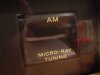
Speaking of parts, does anyone have any idea where I can get two of these tuning eye covers? The ones in my 600 are all warped. They look exactly the same as the one used in my 400, but I have yet to see any for sale anywhere.

Is the lead in the second photo supposed to be connected to anything? I was looking around under the hood this afternoon and noticed this component coming off of the bass tone control that's not connected to anything.
 

Attachments

  • cover.jpg
    cover.jpg
    92.4 KB · Views: 28
  • lead.jpg
    lead.jpg
    235.2 KB · Views: 32
You should really like the TA600 when it's done, I really like mine very much. I think it has better highs than the rest of my Fisher equipment, TA800, 500-C, and X202B.
 
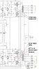
That cap is probably C89 (the only molded cap in that immediate area, the rest are ceramics). One end connects to the down side of the bass pot and the other end connects to R96, a 39K resistor orange, white, orange banded resistor which is in the picture. It connects to the center lug of the bass pot. OR it's mirror on the other channel is C93 and R103.

attachment.php


The Tuning eye covers are gonna be hard to come by. You might find a some old console tuner/preamps from Custom Electra's, Futura's, Ambassadors that are being parted out. Other than that it's gonna be one of those things that is far down the bucket list for it, cosmetically. Unfortunately all of mine are on working units.

Larry
 

Attachments

  • ScreenHunter_49 Sep. 18 19.53.jpg
    ScreenHunter_49 Sep. 18 19.53.jpg
    9.2 KB · Views: 70
Thanks! I had no clue where the cap was supposed to connect to.

The problem I'm currently having and trying to troubleshoot has to do with getting little sound out of one channel. Like I said in an earlier post, there's an imbalance between channels—the right is much weaker than the left. Also, it's doing this weird thing when I turn the balance knob to the left channel. The left channel actually gets louder, like REALLY loud, and the right never goes completely silent. :headscrat

I've tried swapping tubes between A and B channels ... 7189 power tubes, 12AX7 tone control amp and phono tubes, and the 7199 drivers to no avail. The channel that works sounds beautiful. It's clean and full of punch. I just have no clue where to start beyond moving tubes around. The problem persists everywhere ... phono, aux, and FM/AM radio. In fact, I can unplug the problem channel's input from the aux in and notice a trace of audio in the disconnected channel's speaker, as if the good channel is bleeding through.

Any thoughts where I should begin to track this problem down because I haven't a clue!

 
Rather than risk royally screwing up my receiver, I decided that I'm going to bring the TA-600 to my amp guru in Baltimore and have him restore it. He restored a 1964 Sears Silvertone console for me a few years back. He did a phenomenal job and I trust the guy with my vintage gear.

Are there any "must have" safety or sound quality modifications I should request of him?
 
Maybe one of the best things you could have him do is to install some sort of IBAM circuit to allow the bias setting for each output tube to be adjusted individually. Or, if that gets too complicated, at least install a bias control that would allow the bias of all four tubes to be adjusted for optimum operation. Just a thought.....

Dave
 
On a TA-600? I thought that was cathode bias'ed and wasn't adjustable. So i never messed with mine.
 
Fairly easy to make the overall bias adjustable on the TA-600. Add a pot and change two resistors.

Dave
 
Do tell, please. Mine is the 50001-59999 version with 7247's if that makes any difference. Everything below that uses 7199's.

attachment.php


Manual for this version here.....
 

Attachments

  • ScreenHunter_50 Sep. 22 17.13.jpg
    ScreenHunter_50 Sep. 22 17.13.jpg
    59.7 KB · Views: 64
Larry -- Change R158 and 159 to both become 2.7K resistors, separate them where they join, and attach the outside terminals of a 5K pot (even .10 watt rating is fine) between them. Attach the four grid return resistors to the wiper, and there ya go. If you don't like the direction of current change versus the direction of rotation on the pot, then swap the two outside terminal connections.

You could also install individual 10 ohm cathode resistors between each cathode terminal and the now labeled "cathode buss" to measure individual tube current draw if you want. Just remember that your meter leads go between the cathode buss, and each tube cathode terminal when making such measurements. Otherwise , just measure between the cathode buss and ground, and adjust the bias control to achieve the indicated 21 volts at the cathode buss line.

If you opt to lower current flow through the output tubes with this control, just remember that you must maintain a minimum required current flow, or the preamp tube heaters won't have enough current flow through them to operate!

You might notice that this approach is very similar to that which Fisher themselves used in the separate amps of their lower console lines. Even though those units had a bias control, they were basically cathode biased amps as well.

I hope this helps!

Dave
 
excuse the 1st grade paint drawing. I think this is what you mean. Then add 10ohm resistors in series on each pin 3. Then read across each 10ohm resistor? You lost me with "CATHODE BUSS" Is that the line that directly connects each pair to balance them to the right of the tubes on the schematic?
attachment.php
 

Attachments

  • 600 bias mod.JPG
    600 bias mod.JPG
    12.6 KB · Views: 70
It's the same principle as the screen buss. Whereas you removed everything from the string of screen connections and connect them together to become the screen buss off which the Screen Stability resistors connect, we do the same thing here. All the items that currently connect to the pin #3 terminals gets disconnected from those terminals, and connected together to form a new cathode buss. Then from the buss, a 10 ohm resistor would connect to each pin #3 for individual tube measurement.

I hope this helps!

Dave
 
Can someone tell me which coupling capacitors I need to replace in my TA-600? I'm trying to read the schematics and am totally lost. The serial number for my unit is 21810. I think they're toast because some have bubbles and are cracked. This could possibly explain the dead channel. They're the WIMA and Mallory branded caps, among another that I can't read.

thanks.
Travis
 
Last edited:
Back
Top Bottom