

You are using an out of date browser. It may not display this or other websites correctly.
You should upgrade or use an alternative browser.
You should upgrade or use an alternative browser.
Fisher X202B
- Thread starter AlTinkster92
- Start date


Thanks Steve, turned out it was a can cap that caused the problem..all the can caps are being looked after.

nj pheonix
Lunatic Member
Can only say I'm envious. (Not in a bad way) I just always figured a visit to Dave's house would be exactly how you described. You get from his threads that he really loves this stuff and he enjoys sharing his knowledge and experience with good humor and patience.
tube-a-lou
Addicted Member
Dave is great, when there's a problem he's always their to help.
Tube
Tube

Repair Plan of Attack
Al's X-202B is one of those rare gems that is just a gorgeous example of the breed. Other than some darkening of the output tube sockets from heat, the unit doesn't appear to have had a tremendous amount of use over its life, and certainly doesn't look like it required a major cleanup at any point to make it look presentable, either. The thing has simply been so well maintained so that no cleanup effort was ever needed.
At some point, someone has serviced the unit, replacing all of the low voltage cathode bypass electrolytic caps, all of the non-Euro-foil coupling caps throughout the line amp and phase inverter stages, and the one single discrete filter cap that decouples the first stage of the phono preamp circuits (being Fisher's best ever and most practical of their premium integrated offerings, the X-202B uses a dual B+ source to feed the phono preamp circuits, shared only with the ultimate integrated unit, the EL34 based X-1000. Even the vaulted 400CX-2 preamp does not use such extensive decoupling of the B+ circuits in its phono preamps). Strangely however, all of the remainder (i.e. vast majority) of the power supply caps were still original. However, despite the unit's overall good looks -- including that of the power supply can caps as well -- looks can always be deceiving.
When we connected Al's amp up, it displayed a wicked hum at initial warmup, that then settled down to a more steady state hum. By pitch, it was determined to be 120 Hz based, so that meant that something in the power supply had gone south. But then there was this separate nonsense of the volume control not fully killing the signal at a minimum setting (other than when turned off of course). Just as Al had said, a minimum volume control setting produced a very nice listening level in both channels, with the tone and balance controls all operating as they normally would. The loudness control did in fact function as well -- it's just that you couldn't get the volume control up enough "out of the weeds" for its effects to be noticed with the condition the unit was in.
The huge (new) clue was that the phantom minimum volume setting signal was a mono signal out of both channels -- not a stereo signal, even though the unit was set for stereo operation. That meant that unwanted mixing was taking place within the unit as well.
Volume controls that won't turn down, channel mixing, and goofy hum -- that all occur at once -- make a strange enough bag of symptoms to almost automatically go after potential grounding issues right away. But some quick tests proved that was not the case. So with that, the unit was unhooked and put on the bench, the bottom cover removed, and the schematic consulted.
A little study revealed that specifically if C51B opened up within one of the can caps, it would in fact create all of the symptoms at hand. With jumper clips, C51B was then jumped with a suitable external test cap and sure enough, all of the symptoms immediately disappeared. The hum was gone, the volume turned completely down, and there was no more mixing of the stereo signals.
If anything, this shows why power supply caps in the latter distribution stages of the power supply are often called decoupling caps. They provide a virtual zero impedance path to ground for any AC signals that would otherwise be present there from the two channels, preventing them from moving between the channels, or between other stages within the same channel that are connected to the same B+ supply point.
With one cap within one can cap causing all the ruckus then, but all of the power supply caps still being original except for the one mentioned previously, the decision was made to replace all of the remaining original power supply caps -- and while I'm at it, also install Screen Stability and cathode current monitoring resistors in the output stages as well.
Parts were ordered yesterday to accommodate all the repairs. The single high side doubler cap can will be replaced with a (virtual) exact original (a quad 50 uF cap for a single 200 uF cap), and the main quad decoupling cap can also be replaced with an exact original (with a higher voltage rating). The other two cans each contain dual caps that will be neatly replaced with discrete caps under the hood.
With that then, the tear down will begin, with a few before pics offered for posterity:
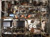
1. The X-202B is a busy chassis for sure. Fisher chassis usually are, but this one is no doubt one of their busiest.
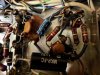
2. The previous tech did the snip and tack approach to replacing the components mentioned earlier, as can be seen by the pig tails that remain from the original cathode bypass cap shown in this pic. It's not my style, but the job was done neatly enough, and the approach does allow for max work to be done in the least amount of time. Ultimately, with good connections, the unit performs the same whether the old components were completely removed, or just snipped out.
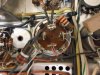
3. Looks can in fact be deceiving. This cap has all the physical appearances of being in great shape, but the internal cap connected to the terminal located at high noon on this bad boy is electrically missing in action.
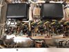
4. While I'm in there, the output stages will get a face lift as well. Not only will it add a significant amount of safety for the tubes, but it will also allow the output tubes to be adjusted for optimum DC bias and balance, since those controls are already provided on the X-202B.
More as parts arrive, and the work unfolds.
Dave
Al's X-202B is one of those rare gems that is just a gorgeous example of the breed. Other than some darkening of the output tube sockets from heat, the unit doesn't appear to have had a tremendous amount of use over its life, and certainly doesn't look like it required a major cleanup at any point to make it look presentable, either. The thing has simply been so well maintained so that no cleanup effort was ever needed.
At some point, someone has serviced the unit, replacing all of the low voltage cathode bypass electrolytic caps, all of the non-Euro-foil coupling caps throughout the line amp and phase inverter stages, and the one single discrete filter cap that decouples the first stage of the phono preamp circuits (being Fisher's best ever and most practical of their premium integrated offerings, the X-202B uses a dual B+ source to feed the phono preamp circuits, shared only with the ultimate integrated unit, the EL34 based X-1000. Even the vaulted 400CX-2 preamp does not use such extensive decoupling of the B+ circuits in its phono preamps). Strangely however, all of the remainder (i.e. vast majority) of the power supply caps were still original. However, despite the unit's overall good looks -- including that of the power supply can caps as well -- looks can always be deceiving.
When we connected Al's amp up, it displayed a wicked hum at initial warmup, that then settled down to a more steady state hum. By pitch, it was determined to be 120 Hz based, so that meant that something in the power supply had gone south. But then there was this separate nonsense of the volume control not fully killing the signal at a minimum setting (other than when turned off of course). Just as Al had said, a minimum volume control setting produced a very nice listening level in both channels, with the tone and balance controls all operating as they normally would. The loudness control did in fact function as well -- it's just that you couldn't get the volume control up enough "out of the weeds" for its effects to be noticed with the condition the unit was in.
The huge (new) clue was that the phantom minimum volume setting signal was a mono signal out of both channels -- not a stereo signal, even though the unit was set for stereo operation. That meant that unwanted mixing was taking place within the unit as well.
Volume controls that won't turn down, channel mixing, and goofy hum -- that all occur at once -- make a strange enough bag of symptoms to almost automatically go after potential grounding issues right away. But some quick tests proved that was not the case. So with that, the unit was unhooked and put on the bench, the bottom cover removed, and the schematic consulted.
A little study revealed that specifically if C51B opened up within one of the can caps, it would in fact create all of the symptoms at hand. With jumper clips, C51B was then jumped with a suitable external test cap and sure enough, all of the symptoms immediately disappeared. The hum was gone, the volume turned completely down, and there was no more mixing of the stereo signals.
If anything, this shows why power supply caps in the latter distribution stages of the power supply are often called decoupling caps. They provide a virtual zero impedance path to ground for any AC signals that would otherwise be present there from the two channels, preventing them from moving between the channels, or between other stages within the same channel that are connected to the same B+ supply point.
With one cap within one can cap causing all the ruckus then, but all of the power supply caps still being original except for the one mentioned previously, the decision was made to replace all of the remaining original power supply caps -- and while I'm at it, also install Screen Stability and cathode current monitoring resistors in the output stages as well.
Parts were ordered yesterday to accommodate all the repairs. The single high side doubler cap can will be replaced with a (virtual) exact original (a quad 50 uF cap for a single 200 uF cap), and the main quad decoupling cap can also be replaced with an exact original (with a higher voltage rating). The other two cans each contain dual caps that will be neatly replaced with discrete caps under the hood.
With that then, the tear down will begin, with a few before pics offered for posterity:
1. The X-202B is a busy chassis for sure. Fisher chassis usually are, but this one is no doubt one of their busiest.
2. The previous tech did the snip and tack approach to replacing the components mentioned earlier, as can be seen by the pig tails that remain from the original cathode bypass cap shown in this pic. It's not my style, but the job was done neatly enough, and the approach does allow for max work to be done in the least amount of time. Ultimately, with good connections, the unit performs the same whether the old components were completely removed, or just snipped out.
3. Looks can in fact be deceiving. This cap has all the physical appearances of being in great shape, but the internal cap connected to the terminal located at high noon on this bad boy is electrically missing in action.
4. While I'm in there, the output stages will get a face lift as well. Not only will it add a significant amount of safety for the tubes, but it will also allow the output tubes to be adjusted for optimum DC bias and balance, since those controls are already provided on the X-202B.
More as parts arrive, and the work unfolds.
Dave
Attachments

tube-a-lou
Addicted Member
They always do, even spot my trusty KX200 looks great on the inside.
Tube
Tube
Parts Just Arrived
Yeah, I'm havin' fun now!
The bad can cap has had all the leads originally connected to it carefully disconnected, standing ready for the new parts to begin installation.
In fairness to the manufacturer of the original can cap, the section that failed likely did not fail within the actual cap media, but rather, at the actual terminal itself. The terminal to that cap section is quite loose, and has apparently broken off at some point underneath the bakelite end piece -- and THAT likely happened because of the very tightly stretch 8.2K 2 watt resistor that supplies power to that terminal.
With there being significant tension on that terminal by this resistor, coupled the natural flexing of the chassis that would occur with movement of the unit over the last 50 years, it apparently final gave up and snapped. This would also explain the lack of a gradual deterioration of performance, and support Al's comment that all of the symptoms happened all at once.
Pics:
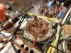
1. All the old leads have been removed from the defective cap, ready for the new can to be installed. Since they weren't removed with the usual snip and tack approach, it will be difficult to tell that the can has been replace when this work is finished.
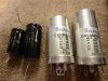
2. New stuff.
At any rate, the repair work can now get underway. Back when there's more to report.
Dave
Yeah, I'm havin' fun now!
The bad can cap has had all the leads originally connected to it carefully disconnected, standing ready for the new parts to begin installation.
In fairness to the manufacturer of the original can cap, the section that failed likely did not fail within the actual cap media, but rather, at the actual terminal itself. The terminal to that cap section is quite loose, and has apparently broken off at some point underneath the bakelite end piece -- and THAT likely happened because of the very tightly stretch 8.2K 2 watt resistor that supplies power to that terminal.
With there being significant tension on that terminal by this resistor, coupled the natural flexing of the chassis that would occur with movement of the unit over the last 50 years, it apparently final gave up and snapped. This would also explain the lack of a gradual deterioration of performance, and support Al's comment that all of the symptoms happened all at once.
Pics:
1. All the old leads have been removed from the defective cap, ready for the new can to be installed. Since they weren't removed with the usual snip and tack approach, it will be difficult to tell that the can has been replace when this work is finished.
2. New stuff.
At any rate, the repair work can now get underway. Back when there's more to report.
Dave
Attachments

Oh boy....My nightmare from Hell unit. Naptown has one that has a hum(or did), I looked at it sporadically for over a year and could never figure it out. I think we narrowed it down to a grounding problem, but FISHER did the Daisy chain grounding on this model and we never did get rid of it.
Hope he reads this thread.
Hope he reads this thread.
Did the hum develop on its own in the unit when stock? Or was it apparent after work was done to the unit?
Dave
Dave
I don't remember if the hum was there before the recap or not. It was definately in one channel as i remember it and it was affected by the mixer pot (can't remember the name of it but it's has to do with how the stereo and mono is mixed up in the upper right hand corner of the front panel.). Hell I don't even know if he still has it or not.

fred soop
Super Member
.....
apparently broken off at some point underneath the bakelite end piece -- and THAT likely happened because of the very tightly stretch 8.2K 2 watt resistor that supplies power to that terminal.
With there being significant tension on that terminal by this resistor, coupled the natural flexing of the chassis that would occur with movement of the unit over the last 50 years, it apparently final gave up and snapped.
.....
Check section 2.6.6 (page 63) of this document, Collins Radio Quality Standards. This would not have happened if those standards had been followed.
http://www.jptronics.org/radios/Collins/Quality/collins_quality.1.pdf

Naptown Rob
Ponographer
Did the hum develop on its own in the unit when stock? Or was it apparent after work was done to the unit?
Dave
Oh, the tangled history on mine...a (non B)202.
Let me see if I can remember the saga accurately.
Came from another AK'er, stock, and developed a hum.
I replaced the can caps & a few others, but I'm no real tech and I hit a dead end.
Passed it on to Larry. He has less hair now. Nothing like an intermittent problem when you want to have fun. The hum would come & go as the chassis was flexed.
It's currently with a fairly brilliant fellow in Virginia (found him through yet another AKer, gotta love this place). He did an excellent job on a pair of McIntosh amps for me & has had the 202 for a while now going through it methodically & meticulously. I should be picking it up soon.
Not the simplest units to work on, but boy - when they sound right, they sound incredible! I've never heard another amp quite like it.
Nap -- I've got an X-202 myself, and it is a special amp indeed. I picked up mine as a sold for parts offering and was able to breathe some new life back into it. You might have seen my thread on that effort here:
http://www.audiokarma.org/forums/showthread.php?t=551073
For the record, it is extremely quiet through my Cornwalls with the volume at minimum, and only displays a soft hiss at elevated volume settings when phono is selected.
Good luck with yours, and I hope it gets all straightened around for you!
Dave
http://www.audiokarma.org/forums/showthread.php?t=551073
For the record, it is extremely quiet through my Cornwalls with the volume at minimum, and only displays a soft hiss at elevated volume settings when phono is selected.
Good luck with yours, and I hope it gets all straightened around for you!
Dave
A Plan Coming Together
Work progresses in between the barnyard Fisher 400 receiver and family events.
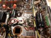
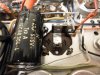
1. Work on installing the new can cap where the defective one was is in the final stages now.
2. Since the old low side doubler can cap is being replaced by discrete components, some provision needs to be made to replace the connection terminals that the old can cap provided. In this case however, only one new terminal needs to be provided, since the lead from the one terminal of this cap that went over to the high side doubler cap is now replaced by the lead of the new discrete cap that replaces it going directly over to the high side cap.
Bending the terminals carefully over then not only preserves what was likely still a good can cap, but also provides a good platform to solder a new terminal board onto to effect a new connection terminal to replace the old terminal of the other cap that was a part of the low side doubler cap can. The new terminal board has been oriented in such a way that the 8.2K resistor feeding the new cap can on the lower deck now has plenty of slack so that the damage that happened to the old cap can cannot happen again to the new one.
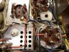
3. A plan is starting to come together. Space has been, and is still in the process of being cleared out, to allow space for the new discrete caps that make up the old low side doubler can cap. It has been carefully planned so that the new caps will not cover up any of the ventilation holes drilled in the chassis. Overall when finished, the work will certainly not have the look of the original build, however, neither should it draw attention to itself as being out of place with the quality of the original build, either.
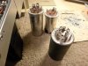
4. The cardboard cover from the old high side doubler can cap fits nicely over the new can cap for that position. Appearance wise then, there will be no change to the top side look of the amplifier. Other than having 4 terminals underneath on the new can (all connected together), there will be little change to the appearance this area under the chassis when finished as well.
More as more is available.
Dave
Work progresses in between the barnyard Fisher 400 receiver and family events.
1. Work on installing the new can cap where the defective one was is in the final stages now.
2. Since the old low side doubler can cap is being replaced by discrete components, some provision needs to be made to replace the connection terminals that the old can cap provided. In this case however, only one new terminal needs to be provided, since the lead from the one terminal of this cap that went over to the high side doubler cap is now replaced by the lead of the new discrete cap that replaces it going directly over to the high side cap.
Bending the terminals carefully over then not only preserves what was likely still a good can cap, but also provides a good platform to solder a new terminal board onto to effect a new connection terminal to replace the old terminal of the other cap that was a part of the low side doubler cap can. The new terminal board has been oriented in such a way that the 8.2K resistor feeding the new cap can on the lower deck now has plenty of slack so that the damage that happened to the old cap can cannot happen again to the new one.
3. A plan is starting to come together. Space has been, and is still in the process of being cleared out, to allow space for the new discrete caps that make up the old low side doubler can cap. It has been carefully planned so that the new caps will not cover up any of the ventilation holes drilled in the chassis. Overall when finished, the work will certainly not have the look of the original build, however, neither should it draw attention to itself as being out of place with the quality of the original build, either.
4. The cardboard cover from the old high side doubler can cap fits nicely over the new can cap for that position. Appearance wise then, there will be no change to the top side look of the amplifier. Other than having 4 terminals underneath on the new can (all connected together), there will be little change to the appearance this area under the chassis when finished as well.
More as more is available.
Dave
Attachments
Looking good Dave, am sure this amp will outlast me and probably good for many more years. How are the 7591's (if you've had the chance to check em...know your busy.) AL
Update
With the barn-find 400 receiver now fully resuscitated, I can get back to Al's X-202B. I had started it so as to get the parts order placed and make sure they would work when received, but the barnyard receiver had been ahead of it, so it needed to get finished up first.
In the X-202, the B+ end of the power supply is completely finished now, with new caps for the doubler, and all the caps down stream from it. The high side doubler can cap was replaced with a suitable new can, while the old low side doubler can cap remains in place, with new discrete components doing the job under the hood.
The original B+ distribution can that had one section go open due to the broken terminal has also been completely replaced now. The original resistor that placed so much stress on the old can cap terminal has been reinstalled in a manner that will eliminate that type of damage from happening again.
Next door in the output stage, the old screen and cathode wiring has been disconnected, and will be discarded because it is brittle as can be. Orange wire has turned brown, and blue to almost black. The output tubes in this sucker have run pretty darn hot. In any event, the wiring will all be replaced with new, along with the installation of the Screen Stability and current sampling cathode resistors. When this area is finished, the heater/bias supply is all that remains, which should go fairly quickly since the plan of attack for that area has already be developed.
Pics include:
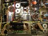
1. The finished B+ power supply. With some careful rearrangement, space was made for the new 220 uF low side doubler cap, and the new 47 uF screen decoupling cap that also resided in the old low side doubler can cap. Both of the new caps have been affixed to the chassis with sealant, so there won't be any problems of them moving around or rattling underneath. You can also see the four sections of the new high side doubler can cap all wired together to make up the 200 uF value of the original can cap used in that position.
The resistors used in the B+ dropping network on the new clamp mounted can cap all measured within 2% of required value, so they were deemed plenty healthy to return to work. The finished look of the overall area isn't stock of course, but neither does it draw attention to itself either, which is always one of my goals when such work is performed.
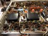
2. On the other hand, the output stages are in a total disarray at this point, with old wiring ready to be pulled out and new installed, along with the current sampling and Screen Stability resistors as well.
3. A little Armorall on the old high side doubler can cap cardboard cover has it looking like new in place over the new cap.
This one is moving along pretty well now. Should have it finished, along with a performance check by the end of the week.
Back with more when there is more.....
Dave
With the barn-find 400 receiver now fully resuscitated, I can get back to Al's X-202B. I had started it so as to get the parts order placed and make sure they would work when received, but the barnyard receiver had been ahead of it, so it needed to get finished up first.
In the X-202, the B+ end of the power supply is completely finished now, with new caps for the doubler, and all the caps down stream from it. The high side doubler can cap was replaced with a suitable new can, while the old low side doubler can cap remains in place, with new discrete components doing the job under the hood.
The original B+ distribution can that had one section go open due to the broken terminal has also been completely replaced now. The original resistor that placed so much stress on the old can cap terminal has been reinstalled in a manner that will eliminate that type of damage from happening again.
Next door in the output stage, the old screen and cathode wiring has been disconnected, and will be discarded because it is brittle as can be. Orange wire has turned brown, and blue to almost black. The output tubes in this sucker have run pretty darn hot. In any event, the wiring will all be replaced with new, along with the installation of the Screen Stability and current sampling cathode resistors. When this area is finished, the heater/bias supply is all that remains, which should go fairly quickly since the plan of attack for that area has already be developed.
Pics include:
1. The finished B+ power supply. With some careful rearrangement, space was made for the new 220 uF low side doubler cap, and the new 47 uF screen decoupling cap that also resided in the old low side doubler can cap. Both of the new caps have been affixed to the chassis with sealant, so there won't be any problems of them moving around or rattling underneath. You can also see the four sections of the new high side doubler can cap all wired together to make up the 200 uF value of the original can cap used in that position.
The resistors used in the B+ dropping network on the new clamp mounted can cap all measured within 2% of required value, so they were deemed plenty healthy to return to work. The finished look of the overall area isn't stock of course, but neither does it draw attention to itself either, which is always one of my goals when such work is performed.
2. On the other hand, the output stages are in a total disarray at this point, with old wiring ready to be pulled out and new installed, along with the current sampling and Screen Stability resistors as well.
3. A little Armorall on the old high side doubler can cap cardboard cover has it looking like new in place over the new cap.
This one is moving along pretty well now. Should have it finished, along with a performance check by the end of the week.
Back with more when there is more.....
Dave
Attachments
You're correct, Don. But I wouldn't call the X-202B the "baby" brother of the X-1000 by any means. Maybe the "younger" brother, as it retains all the important features of the X-1000, while only producing slightly less power output.
As a result, I have always felt that the X-202B represents the most practical design of all of Fisher's premium offerings, giving the consumer the biggest bang for their premium bucks.
Dave
As a result, I have always felt that the X-202B represents the most practical design of all of Fisher's premium offerings, giving the consumer the biggest bang for their premium bucks.
Dave