plndrm
Madman Across a Body of Semi-Viscous Ferrofluid
Hi Everyone,
Sorry for the length of the post…
I am looking to repair my fathers 4300 that is now in my possession, I broke it – I bought it. He ordered it on 5-Oct-1975 from a dealer in South (New) Jersey for $825. The following items were included; “Handbook of Instructions” (seriously who calls it that?), a foldout schematic (dated Christmas 73’), a full line brochure (predates the 4400, as it isn't included in the lineup), a SQA-2B adaptor, and the original walnut cabinet. Also included in my “purchase”, two KEF 104ab’s and their original metal stands, and a Harman Kardon 44+ CD4 demodulator.
Like I said I was young and stupid and I blew up, well more like fried, the 4300 sometime in the late 90’s by connecting a JL Audio 12w6-1ohm driver to one of the front channels, don't remember which one it was. Someone here will be able to tell once I start describing what I think is toasted.
I have experience soldering TO boards, I build guitar pedals and learned how to r&r electrical components on my 81 year old Hammond Concert Model E. That was a project! But I’m sure to learn something new somewhere along the repair.
The purpose for creating this thread is to primarily gain insight on what I may need to look for above and beyond the components that have degraded due to age (Electrolytic, VD1212’s, ect). There are plenty of other threads covering troublesome components; I don’t want to piss off the search police. Those known troublesome items will all be replaced.
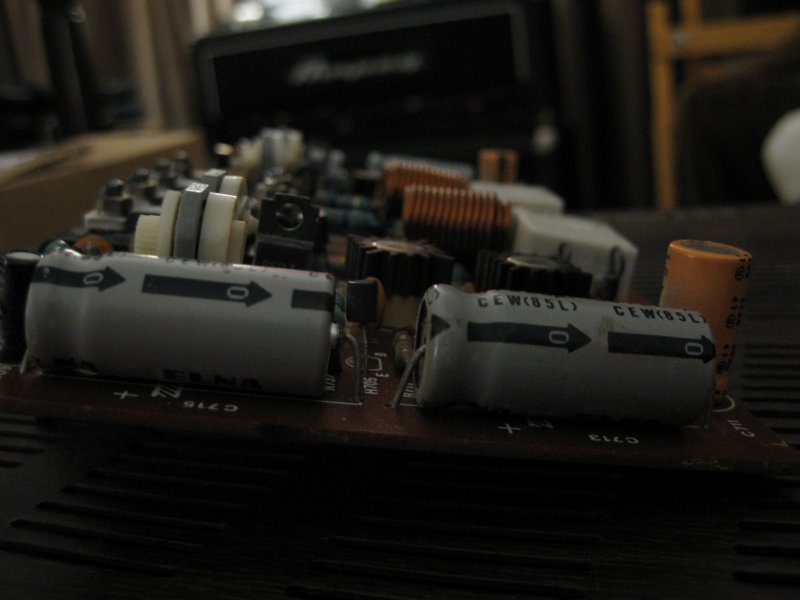
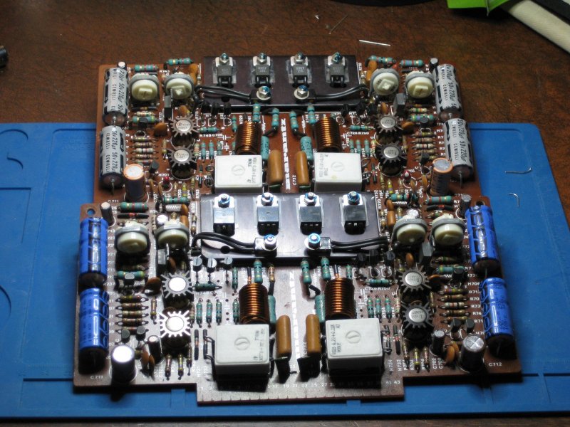
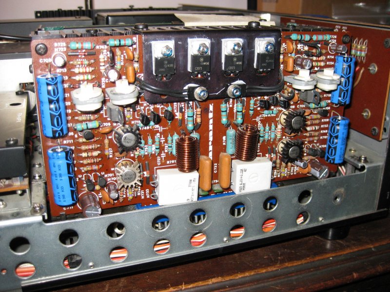
Starting with the right P700 that has physical component damage. This may be a silly question but, any component I replace on the damaged side needs to be mirrored on the other channel on the same board AND both channels on the other P700 board correct?
On the left side of the board as installed the possible damaged components are:
H708-2SC627-plastic riser is yellowed but Hfe was within spec. The one transistor I don’t see a direct replacement for, hoping it survived. These are marked Fujitsu.
H711-2SC458B-shorted B to C. Transistor tester thinks it’s a 0.56ohm resistor.
H713-2SD357-B Leg is open. Transistor tester can’t detect it.
H714-2SB527-Shorted B to C to E. Transistor tester thinks it’s two resistors, B-C: 1.27ohm, C-E: 87.0ohm.
H717-2SC945-shorted B to C to E. Transistor tester thinks it’s two resistors, B-C: 1.59ohm, C-E: 16.8ohm.
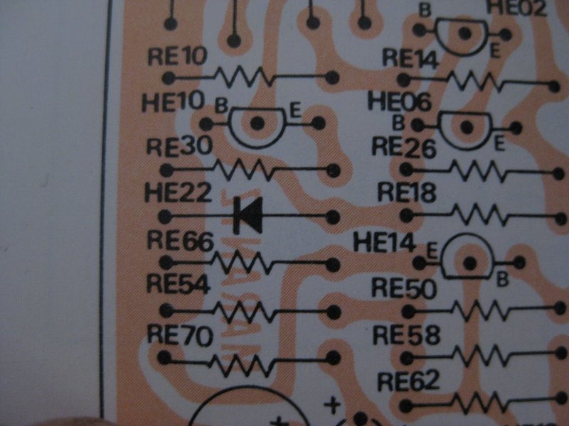
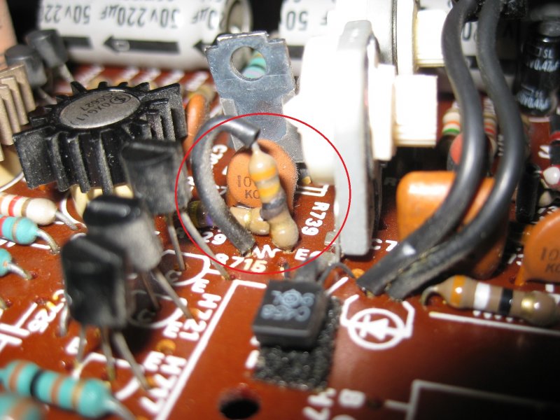
R715-33ohm-burnt. For some reason the Service Manual doesn’t list resistors R715 & R716 but based on the Orange/Orange/Black/Gold banding I think it should be 33ohm. Even though it is cooked it still reads 33.5ohms, will be replacing it.
R745-100ohm-burnt.
Should I replace every transistor on the board, well maybe with the exception of the four 2SC627’s or check for shorts between legs? I figured if I have to remove to test then why subject them to more heat stress, just replace with modern equivalents.
After I get both P700’s back to spec I need to replace the output transistors. I fried two of them too.
The bottom pair of power transistors on the large heat sink (2SA745/2SC1403), my transistor tester thinks A745 is two resistors in parallel, does not detect it as a PNP transistor. C1403 is shorted between B and C.
Regarding 2SA745/2SC1403, is the consensus to replace it with MJ21193/MJ21194? Do I need to worry about Hfe and Ft being that off? Are there substitutes that are not a TO-3 form factor that might be closer spec wise to the originals?
Should I pull and check the transistors in the phase converter board, PM01? Recapping CM01-CM05.
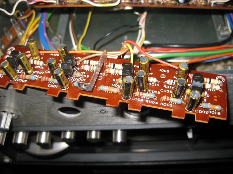
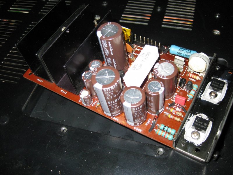
Finally, I found a broken solder lug on the power supply board (P800) that runs to the main transformer Digikey and Mouser do not have anything that looks to match what broke, any suggestions where to source an original looking piece?
Sorry for the long post, I hope I made sense through it all.
Marc
Here is the phantom resistor R715 with a nice burnt ring on it.
This picture is before I de-soldered all the connections on the power supply board. The solder lug on the far left was broken in two right where it entered the board, held on just by solder.

Sorry for the length of the post…
I am looking to repair my fathers 4300 that is now in my possession, I broke it – I bought it. He ordered it on 5-Oct-1975 from a dealer in South (New) Jersey for $825. The following items were included; “Handbook of Instructions” (seriously who calls it that?), a foldout schematic (dated Christmas 73’), a full line brochure (predates the 4400, as it isn't included in the lineup), a SQA-2B adaptor, and the original walnut cabinet. Also included in my “purchase”, two KEF 104ab’s and their original metal stands, and a Harman Kardon 44+ CD4 demodulator.
Like I said I was young and stupid and I blew up, well more like fried, the 4300 sometime in the late 90’s by connecting a JL Audio 12w6-1ohm driver to one of the front channels, don't remember which one it was. Someone here will be able to tell once I start describing what I think is toasted.
I have experience soldering TO boards, I build guitar pedals and learned how to r&r electrical components on my 81 year old Hammond Concert Model E. That was a project! But I’m sure to learn something new somewhere along the repair.
The purpose for creating this thread is to primarily gain insight on what I may need to look for above and beyond the components that have degraded due to age (Electrolytic, VD1212’s, ect). There are plenty of other threads covering troublesome components; I don’t want to piss off the search police. Those known troublesome items will all be replaced.
Starting with the right P700 that has physical component damage. This may be a silly question but, any component I replace on the damaged side needs to be mirrored on the other channel on the same board AND both channels on the other P700 board correct?
On the left side of the board as installed the possible damaged components are:
H708-2SC627-plastic riser is yellowed but Hfe was within spec. The one transistor I don’t see a direct replacement for, hoping it survived. These are marked Fujitsu.
H711-2SC458B-shorted B to C. Transistor tester thinks it’s a 0.56ohm resistor.
H713-2SD357-B Leg is open. Transistor tester can’t detect it.
H714-2SB527-Shorted B to C to E. Transistor tester thinks it’s two resistors, B-C: 1.27ohm, C-E: 87.0ohm.
H717-2SC945-shorted B to C to E. Transistor tester thinks it’s two resistors, B-C: 1.59ohm, C-E: 16.8ohm.
R715-33ohm-burnt. For some reason the Service Manual doesn’t list resistors R715 & R716 but based on the Orange/Orange/Black/Gold banding I think it should be 33ohm. Even though it is cooked it still reads 33.5ohms, will be replacing it.
R745-100ohm-burnt.
Should I replace every transistor on the board, well maybe with the exception of the four 2SC627’s or check for shorts between legs? I figured if I have to remove to test then why subject them to more heat stress, just replace with modern equivalents.
After I get both P700’s back to spec I need to replace the output transistors. I fried two of them too.
The bottom pair of power transistors on the large heat sink (2SA745/2SC1403), my transistor tester thinks A745 is two resistors in parallel, does not detect it as a PNP transistor. C1403 is shorted between B and C.
Regarding 2SA745/2SC1403, is the consensus to replace it with MJ21193/MJ21194? Do I need to worry about Hfe and Ft being that off? Are there substitutes that are not a TO-3 form factor that might be closer spec wise to the originals?
Should I pull and check the transistors in the phase converter board, PM01? Recapping CM01-CM05.
Finally, I found a broken solder lug on the power supply board (P800) that runs to the main transformer Digikey and Mouser do not have anything that looks to match what broke, any suggestions where to source an original looking piece?
Sorry for the long post, I hope I made sense through it all.
Marc
Here is the phantom resistor R715 with a nice burnt ring on it.
This picture is before I de-soldered all the connections on the power supply board. The solder lug on the far left was broken in two right where it entered the board, held on just by solder.
Broken_ps_lug
4300 Quad - P800 Power Supply Board - Last lug on the left is broken in two where it enters the...