• The move to the new server is done. There are some software and database maintenance updates in process. This has us passing the hat around to help out. We appreciate any donations. Seriously, even a dollar helps. The payment page may be found here - https://www.audiokarma.org/support.html

Fixed! 4300 Repair/Restore

Sometimes a picture is helpful

MikeRam, how did you end up shoe horning the two Wima 4.7uF caps @ CE13 & CE16? I temporarily removed RE69 & RE71 to gain a few mm but all my > 50v 4.7uF caps for CE17 & CE20 have a diameter of 10mm (Nichi UKZ 100v is 12.5mm) and with the very short leads on the Wimas its going to be a lot of fun getting them in.
 
Last edited:
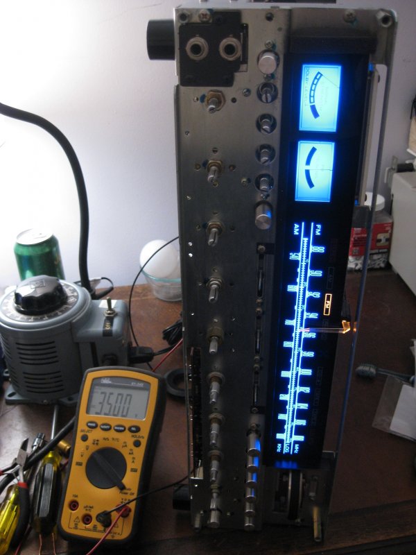
It's alive, well without the amp cards in it.
Found out that no matter how much I looked I still had one cap backwards, C413 on phono board. Who designs a circuit with the inner pair of through holes opposite of the outer pair?!? Caught it before anything went catastrophic but swapped it out because it smelled overly warm.
I checked all the pins on both amp cards for continuity/shorts and found none so hopefully everything goes smoothly.

 
Amp cards went in and the 100w bulb came on very dim, I could see the filament. Then smoke, fudge, R745 on the left amp board is crispy, this is the other card in the receiver. So I have something wrong with this card too, weird that it's the same exact resistor that went boom the first time. FWIW this is with both main and remote speaker outputs OFF.

I checked the other card and it looks good so with just the right amp card in the bulb lights up dim for a 1/2 a second and goes out. I was brave and turned the main speaker switch on and the speaker protection relay clicked! So the good news is it came out of protection.

Is it normal for the bulb to light up just a little bit and fade out within two seconds of turning the receiver on?
I'll pull all four output transistors again and check for a short as well as most of the transistors on this other p700 board and report back to myself.
 
It is normal for the bulb to light up for a second or two and go dim. That is the current charging up all of the caps at power up. How dim it gets depends on the current draw of the amp and the wattage of the bulb. A low watt bulb on a larger amp might not dim very much, but it should dim some. I use a 60W bulb on amps under about 45 wpc, and a 100W bulb on larger amps. Others may recommend different ratings.
 
Found two more bad output transistors A745/C1403, I think they are H001 & H002 on the schematic. Unfortunately the schematic has a typo on the pair of P700 boards, the top one has the channels labeled RL/FL and the lower one has the channels labeled RL/RR. I plugged in headphones with the right amp card in and had audio (not great, and a ground hum) on the right channel.
2SA745 was shorted between E & C and passing 0.093v between E->B, B->E, C->B, B->C (positive connection listed first). Measuring 2SC1403 B->C had a reading of 0.297v, not good, and reversing the leads I measured 0.713v, again not good. Every other combination resulted in a OL.
Also pulled were both 2SC458's @ H711 & H712. H711 had a hFE reading of 170 and a Vf of 0.702v. H712 had a hFE reading of 169 and Vf of 0.721. They will not be going back in regardless of the readings.
The readings for 2SB527 were, hFE: 91 and 110 respectively, and Vf of 0.643v and 0.645v. They will not be going back in either.
The readings for 2SD357 were, hFE: 44 and 79 respectively, Vf readings were identical @ 0.638v.

Should i really be pulling every transistor on this side and test? I think I may have swapped cards many years ago and blown out the two output transistors at that time.
Its getting there...
Anything I'm missing?

Thanks,
marc
 
Little update.
Replaced the two lower two (FL) output transistors, A745 and C1403 on the left heat sink, and the four transistors @ H713-H716, as well as the two C458’s @ H711 & H712, and the resistor at R745. Plugged it back into the DBT and thankfully no shorts.
Was able to set bias and offset via R739/R740 (12mV) and R721/R722 (0V) on this side.

I ran into an issue on the original bad P700. I can’t set the left side of the card to 12mV, I only get 0V between pins 11(+) and 9(-). I can achieve an offset of 0V between pins 13(+) and 15(-) on this side of the card and am able to set the right side with no issues.

Where do I test from here? Solder pads all look good no bridges that I can see under a lens. Did I screw something up in the preamp?

I hooked up an audio source to CD-4/Aux inputs and the left channel sounds fantastic and of course nothing out of the right channel. Can I safely swap P700 cards (and dbt test first) now that I have eliminated any short circuits?

Edit: Both channels are working through headphones. I pulled the right P700 card out and checked it over again, desoldered what might have been a bad solder joint but couldn’t tell, had continuity before and after I did so. Still getting 0V between pins 11 and 9, it did fluctuate about 0.1mV while I was listening to some Alice In Chains through a mini disc player.
 
Last edited:
So the right channel (headphones) occasionally drops out when the unit is switched on. Oddly I can hear what I think is the right channel briefly when I switch off the power, this is before the caps fully discharge and the left channel fades out to nothing (distortion increases as the caps discharge).
Secondly when the volume out of the source is increased and the music itself (dynamic?) becomes louder/more complex I noticed that with the mini probes on 11(+) and 9(-) the voltage increases from 0.0mV to about 0.4mV. Am I measuring the source’s, in this case the minidisc player, output voltage increase?
Could I have another transistor that is failed open that I am missing?
Thanks
 
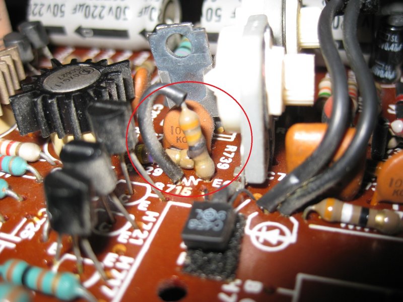
Still pulling and measuring everything on the left side of the right P700 board. I started to remove the massive heat sink to see if the lower output transistors weren't making good contact but I had to stop and eat lunch. While eating lunch I searched for marantz zero bias and spent more time browsing then actually eating. Didn't find any posts that jumped out at me except for one which basically said the problem is right under my nose and I'm looking past it. Damn if it wasn't right, R739 the trim pot is open between B and E on the bias transistor H711. It would also explain why I'm getting different readings when the transistors are soldered in place but the same when they're removed. :idea:

The parts book calls for a 1K ohm (B). Does B mean linear taper in this instance? Thanks.
 
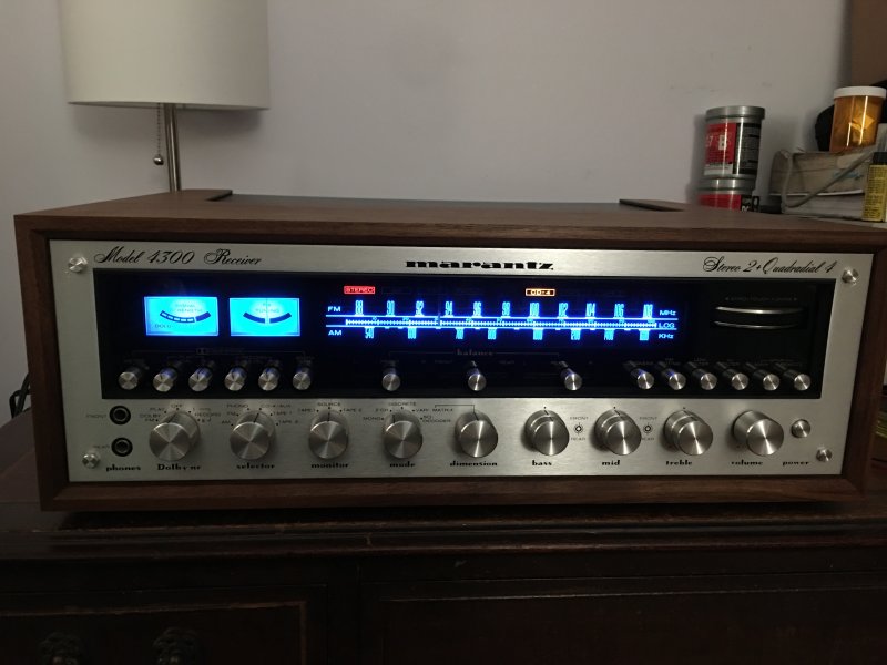
Isn't that a beautiful thing?
While I'm waiting for the last trim pot to arrive I decided to put it in its wooden box to protect it from weekend visitors. I spent half the day with headphones on listening to pretty much every genre and man does it sound good. I listened to some music I remember hearing when I was a kid through it and it felt like I took a trip back in time. That smooth punchy sound is there in every thing I listened to, can't wait for the caps to break in, can it get any better? Unfortunately the cap kit from Falcon UK is stuck in Chicago somewhere in Customs, going on three weeks, hopefully it will make it here before the end of June for the big reveal.
 
Haven't been on the site for a while. That looks awesome and congrats on finding the issue. It always seems like such a simple problem once you find it but it's miserable until then. My 4300 had one channel that hardly had sound and I was pulling my out hair trying to figure it out. It ended up being a broken ground on the shielded signal cable coming from the PM01 Phase Converter board to the P700 Power amp board. The break was hidden so it was a pain to find. Sounds awesome now. Just waiting for a late FedEx shipment with the last transistors and caps to finish off the unit.

Going to use it for playing music at my daughter's wedding coming up. Hope to have it all broken in by then.

Mike
 
Found some time this weekend after running my son's Cub Scout Pack's Pinewood Derby to swap out the bad trim pot. I used a 1k 1/2W Nidec Copal single turn pot because it fit better then the almost 8 dollar Bourns pot. Both were rated at 200 cycles, so I went with the one that fit better. After an hour of warm up I was thrilled that I was able to set the bias to 12mV and the offset stabilized at +/- 0.01mV (the amp channel I toasted). After a check/adjustment of the other three channels I held my breath and connected a pair of old Kenwood's that I bought when I was 14 that live in my cow barn (cows are long gone). IT SANG! **** it was amazing.
The KEF's have been recapped and after 100 hours of break in they will finally be paired up with this 4300.

Thank you. Thank you. Thank you to Steven Tate, MikeRam, catrafter, EastPoint, & USMC Spike for taking the time to read my posts and point me in the right direction. It would still be sitting in a box in my attic if it weren't for your guidance.
 
Hi Everyone,
Sorry for the length of the post…
I am looking to repair my fathers 4300 that is now in my possession, I broke it – I bought it. He ordered it on 5-Oct-1975 from a dealer in South (New) Jersey for $825. The following items were included; “Handbook of Instructions” (seriously who calls it that?), a foldout schematic (dated Christmas 73’), a full line brochure (predates the 4400, as it isn't included in the lineup), a SQA-2B adaptor, and the original walnut cabinet. Also included in my “purchase”, two KEF 104ab’s and their original metal stands, and a Harman Kardon 44+ CD4 demodulator.

Like I said I was young and stupid and I blew up, well more like fried, the 4300 sometime in the late 90’s by connecting a JL Audio 12w6-1ohm driver to one of the front channels, don't remember which one it was. Someone here will be able to tell once I start describing what I think is toasted.
I have experience soldering TO boards, I build guitar pedals and learned how to r&r electrical components on my 81 year old Hammond Concert Model E. That was a project! But I’m sure to learn something new somewhere along the repair.

The purpose for creating this thread is to primarily gain insight on what I may need to look for above and beyond the components that have degraded due to age (Electrolytic, VD1212’s, ect). There are plenty of other threads covering troublesome components; I don’t want to piss off the search police. Those known troublesome items will all be replaced.

Starting with the right P700 that has physical component damage. This may be a silly question but, any component I replace on the damaged side needs to be mirrored on the other channel on the same board AND both channels on the other P700 board correct?
On the left side of the board as installed the possible damaged components are:
H708-2SC627-plastic riser is yellowed but Hfe was within spec. The one transistor I don’t see a direct replacement for, hoping it survived. These are marked Fujitsu.
H711-2SC458B-shorted B to C. Transistor tester thinks it’s a 0.56ohm resistor.
H713-2SD357-B Leg is open. Transistor tester can’t detect it.
H714-2SB527-Shorted B to C to E. Transistor tester thinks it’s two resistors, B-C: 1.27ohm, C-E: 87.0ohm.
H717-2SC945-shorted B to C to E. Transistor tester thinks it’s two resistors, B-C: 1.59ohm, C-E: 16.8ohm.
R715-33ohm-burnt. For some reason the Service Manual doesn’t list resistors R715 & R716 but based on the Orange/Orange/Black/Gold banding I think it should be 33ohm. Even though it is cooked it still reads 33.5ohms, will be replacing it.
R745-100ohm-burnt.

Should I replace every transistor on the board, well maybe with the exception of the four 2SC627’s or check for shorts between legs? I figured if I have to remove to test then why subject them to more heat stress, just replace with modern equivalents.

After I get both P700’s back to spec I need to replace the output transistors. I fried two of them too. :(
The bottom pair of power transistors on the large heat sink (2SA745/2SC1403), my transistor tester thinks A745 is two resistors in parallel, does not detect it as a PNP transistor. C1403 is shorted between B and C.
Regarding 2SA745/2SC1403, is the consensus to replace it with MJ21193/MJ21194? Do I need to worry about Hfe and Ft being that off? Are there substitutes that are not a TO-3 form factor that might be closer spec wise to the originals?

Should I pull and check the transistors in the phase converter board, PM01? Recapping CM01-CM05.

Finally, I found a broken solder lug on the power supply board (P800) that runs to the main transformer Digikey and Mouser do not have anything that looks to match what broke, any suggestions where to source an original looking piece?

Sorry for the long post, I hope I made sense through it all.

Marc

Here is the phantom resistor R715 with a nice burnt ring on it.

This picture is before I de-soldered all the connections on the power supply board. The solder lug on the far left was broken in two right where it entered the board, held on just by solder.

Hi Marc, how are you? Hoping you may be able to help me out. I have a 4300 with a blown fuse, but the fuses I bought to replace do not seem to be working. The unit powers on for one second, then kaput.. Can you tell me precisely what kind of fuse you are using? I would be forever grateful. Thanks so much. -Michael
 
Fuses are the effect, not the cause. Something is causing the fuse to blow. Unless you’re putting a vastly underpowered fuse in there.
 
@MimotriO,

You will need to find the short. This thread provides a pretty good step by step things to test.

DBT
Pull amp boards
Measure PS

I had one with blown power supply diodes and has to replace with a bridge per echowars. I might have replaced both diode bits.

A lot of threads to read over lunch...
 
@MimotriO,

You will need to find the short. This thread provides a pretty good step by step things to test.

DBT
Pull amp boards
Measure PS

I had one with blown power supply diodes and has to replace with a bridge per echowars. I might have replaced both diode bits.

A lot of threads to read over lunch...
Thanks so much, appreciate it!
 
Back
Top Bottom