If you've seen my last post, I accidentally cracked the PCB of my Pioneer SX-50 in a bonehead move. Luckily, only a few traces were damaged, and it looks like an easy fix to me. I'm going to go as slow as I can to ensure I do a proper job on this. However, call me paranoid, but should I worry about a possible loss in performance/quality by repairing the traces with jumper wire?


You are using an out of date browser. It may not display this or other websites correctly.
You should upgrade or use an alternative browser.
You should upgrade or use an alternative browser.
Fixing a broken PCB with jumper wires; will it perform the same as before?
Register to hide this ad

if its the power supply board, I don't see any problems. Some things have critical layout that must be just so in order for it to work right, but thats more when you're talking radio circuits or very high gain circuits where noise might be a problem.
The crack is located right where the filter caps are, so I think that whole section of the board is the power supply section.

Binkman
Lunatic Member
If you've seen my last post,

whoaru99
Epic Member
If you've seen my last post, I accidentally cracked the PCB of my Pioneer SX-50 in a bonehead move. Luckily, only a few traces were damaged, and it looks like an easy fix to me. I'm going to go as slow as I can to ensure I do a proper job on this. However, call me paranoid, but should I worry about a possible loss in performance/quality by repairing the traces with jumper wire?
Even if it were the case, but I think is not in this case, what other choice do you have unless you're going to scour the web for a donor unit?
Even if it were the case, but I think is not in this case, what other choice do you have unless you're going to scour the web for a donor unit?
That's true, I guess I'm just letting this audiophile snake-oil get to my head. All their fancy $1000 cables...


trainbuftony
Electron Herder
Your options include what you have suggested as a repair as well as scouring the web for a used part, or prototyping a brand new board. If i were in your shoes, id use the jumpers, and get back to the music. Techs often do the same thing, because at the end of the day, its just got to work.

sKiZo
Hates received: 92644 43.20°N 85.50°W
Mostly I'd be worried about lifting traces. Make sure the copper is good and clean, and use a hot iron. I pre-tin both the trace and wire, then line things up and hit the iron just long enough to flow the solder that's already there. I'll also dip the wire in flux after heating it a bit just for the best possible flow. Wouldn't try any of this with a cheap low watt pencil iron though.
PS - lots of experience with that, and that's only with one restoration. My QRX-9001 needed 50 patches like you're talking to bridge failing pass through joints on a double sided board. I blunted the end of an ex-acto knife to just more than the width of the traces, and used that to scrape the board to bare copper where needed. Strip the wire and bend that to match the trace before applying. Solder station was set to 725F.
Here's a pic ... the one bare "terminal to nowhere" in the middle shows the trace ready for a jumper.
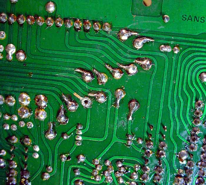
PS - lots of experience with that, and that's only with one restoration. My QRX-9001 needed 50 patches like you're talking to bridge failing pass through joints on a double sided board. I blunted the end of an ex-acto knife to just more than the width of the traces, and used that to scrape the board to bare copper where needed. Strip the wire and bend that to match the trace before applying. Solder station was set to 725F.
Here's a pic ... the one bare "terminal to nowhere" in the middle shows the trace ready for a jumper.
Note that small pieces of wire will "stick" to solder on the iron and lift off! Very annoying. That is one reason I made mine with insulated wire and fairly long. Was also trying to prevent shorts, those traces are small. Board was split so I couldn't just wipe solder over the crack, in some places the traces were lifted quite a bit.
I second the idea of tinning both and just applying the iron enough to melt the junction. More solder on the trace and less on the wire is good. I did this for most of my jumpers.
On signal traces you want to keep the jumpers as short as possible to prevent any stray interference from doubled wires (which may act as an antenna), but if you follow the trace with the wire and tack it down with some hot glue or something, you should be fine.
The hum you hear is one side of that filter cap not making contact, make sure you have both sides connected to the appropriate trace. Snapping the board can also crack adjacent solder joints from the shock wave generated by the board breaking. I had to touch up every single joint anywhere near that break on mine before it would stay out of protection.
I second the idea of tinning both and just applying the iron enough to melt the junction. More solder on the trace and less on the wire is good. I did this for most of my jumpers.
On signal traces you want to keep the jumpers as short as possible to prevent any stray interference from doubled wires (which may act as an antenna), but if you follow the trace with the wire and tack it down with some hot glue or something, you should be fine.
The hum you hear is one side of that filter cap not making contact, make sure you have both sides connected to the appropriate trace. Snapping the board can also crack adjacent solder joints from the shock wave generated by the board breaking. I had to touch up every single joint anywhere near that break on mine before it would stay out of protection.

@Saffire from your other thread...
Honestly, I wouldn't do this repair, and I don't think you really want to either, going by some of your comments in the other thread. The number of hours that you would invest into (hopefully) repairing a $27 amp, an amp that you have already replaced, just doesn't seem a good investment of your time. I looked at recent eBay sales and found that working units have sold for $33 - $69.
If every trace was jumpered, yes the amp should work and sound exactly as before. But on/off cycles create slight temperature cycling which means expansion/contraction cycles, which means that a mechanically compromised PCB, with several makeshift solder joints, would likely never be as reliable over time as an unmolested unit would be. You already said that you learned a valuable lesson, a positive thing, that was the main point of your other thread before others persuaded you to fix it. Choose your battles wisely.
Your broken SX-50 could be kept as a parts unit for possible future repairs to your working amp.
...
Luckily, I managed to snag another SX-50 from OfferUp for $113. My broken SX-50 only cost me $27... But this receiver is just so good, and I can't pass up the chance. Rest assured that I'll fix this receiver someday! For now, it'll just be a cool display in my room.
Honestly, I wouldn't do this repair, and I don't think you really want to either, going by some of your comments in the other thread. The number of hours that you would invest into (hopefully) repairing a $27 amp, an amp that you have already replaced, just doesn't seem a good investment of your time. I looked at recent eBay sales and found that working units have sold for $33 - $69.
If every trace was jumpered, yes the amp should work and sound exactly as before. But on/off cycles create slight temperature cycling which means expansion/contraction cycles, which means that a mechanically compromised PCB, with several makeshift solder joints, would likely never be as reliable over time as an unmolested unit would be. You already said that you learned a valuable lesson, a positive thing, that was the main point of your other thread before others persuaded you to fix it. Choose your battles wisely.
Your broken SX-50 could be kept as a parts unit for possible future repairs to your working amp.
Last edited:
@Saffire from your other thread...
Honestly, I wouldn't do this repair, and I don't think you really want to either, going by some of your comments in the other thread. The number of hours that you would invest into (hopefully) repairing a $27 amp, an amp that you have already replaced, just doesn't seem a good investment of your time. I looked at recent eBay sales and found that working units have sold for $33 - $69.
If every trace was jumpered, yes the amp should work and sound exactly as before. But on/off cycles create slight temperature cycling which means expansion/contraction cycles, which means that a mechanically compromised PCB, with several makeshift solder joints, would likely never be as reliable over time as an unmolested unit would be. You already said that you learned a valuable lesson, a positive thing, that was the main point of your other thread before others persuaded you to fix it. Choose your battles wisely.
Your broken SX-50 could be kept as a parts unit for possible future repairs to your working amp.
Being a broke teen with no job, (thanks corona!) My father is the one who bought me the "new" SX-50. My plan is to fix my current SX-50, and if it actually works, then I'll be giving the new unit to my father. I'm aware of the risks of using a unit with a compromised PCB, but I'd like to think of it as a learning experience. It's my first time tackling a project like this one.

dly66
Addicted Member
Think about it. Some vintage units have wires running along the board completing a circuit (thinking an old HH Scott 344C I was in in the past) and many bare wire jumpers are often used in designs to continue the circuit on another section of board. People who are casting doubt the mend job may last for years. Maybe until the old electronics develop another problem elsewhere in the unit.
I have a couple units that have jumpers in them to keep them going. Serves as a learning experience - figure out how to do a solid hopefully lasting job and see how long it endures. It is that way when you fix anything, especially stuff most people would not think of fixing.
I have a couple units that have jumpers in them to keep them going. Serves as a learning experience - figure out how to do a solid hopefully lasting job and see how long it endures. It is that way when you fix anything, especially stuff most people would not think of fixing.

petehall347
the brandy coffee man
thats why i would solder a long length and cut off when finished . i sometimes nick the wire with a blade and snap it off whilst the blade is holding the wire down .Note that small pieces of wire will "stick" to solder on the iron and lift off! Very annoying
Think about it. Some vintage units have wires running along the board completing a circuit (thinking an old HH Scott 344C I was in in the past) and many bare wire jumpers are often used in designs to continue the circuit on another section of board. People who are casting doubt the mend job may last for years. Maybe until the old electronics develop another problem elsewhere in the unit.
I have a couple units that have jumpers in them to keep them going. Serves as a learning experience - figure out how to do a solid hopefully lasting job and see how long it endures. It is that way when you fix anything, especially stuff most people would not think of fixing.
I am the only person "casting doubt" on the potential mend job.
To do this repair will require multiple advanced technique solder joints. Based on comments by the OP, he has little if any experience soldering, even with standard leg-through-hole-into-an-intact-pad. But this repair will require soldering wire ends to surface tracks/pads. The work is beyond his current skill level.
Even if he somehow manages to do all of these joints perfectly, the PCB will still be broken, and my comments above about heating/cooling and expansion/contraction cycles is valid.
I think the lesson to be learned here is to go with one's own gut instinct and to understand, and accept, one's abilities and to choose projects accordingly. At this point in time if the OP truly wants to learn, and improve his skill set, it would make much more sense to learn basic soldering on a practice machine of some sort, then perhaps do some recapping in small quantities....with through-hole component legs soldered to intact solder pads. Usually people learn to Deoxit and then set bias/offset before any basic component replacement This OP is being encouraged to simply dive into a complex and difficult repair too far beyond his current abilities.
@Saffire 99.9999999% of people in the world could not, and will never be able to, do the repair that is being suggested to you. Those people don't care, and indeed they should not. Everybody is different and every person has their own unique abilities. If you wish to learn to repair vintage electronics, then more power to you. IMO there are more logical places for you to start than this repair. I see too many train wrecks in these forums. I am merely trying to give you an alternative view point to counter the many voices urging you on.
Last edited:
@Saffire
If you proceed:
---any track/pad that you solder to needs to be scraped down to clean copper then tinned before attaching a wire
---wires need to be tinned before joining to a track
---if you can take advantage of a component leg sticking through the board, you can j-hook your jumper wire around that leg to add stability to the joint
---use small, solid core copper wire. The wire should be insulated unless it is very short such that there is no chance of contacting other tracks, solder joints, or anything metal.
---flux is your friend, especially so for novice solderers. The flux that is in the core of solder burns off quickly, but flux is essential for making a strong joint. Get some additional flux and use it generously...then clean it off after the joint cools.
---be aware of what type of components that you are soldering near. What is on the other side of the board where your iron tip is? Small diodes, transistors, and especially polystyrene capacitors, can be damaged by too much or prolonged solder iron heat
If you proceed:
---any track/pad that you solder to needs to be scraped down to clean copper then tinned before attaching a wire
---wires need to be tinned before joining to a track
---if you can take advantage of a component leg sticking through the board, you can j-hook your jumper wire around that leg to add stability to the joint
---use small, solid core copper wire. The wire should be insulated unless it is very short such that there is no chance of contacting other tracks, solder joints, or anything metal.
---flux is your friend, especially so for novice solderers. The flux that is in the core of solder burns off quickly, but flux is essential for making a strong joint. Get some additional flux and use it generously...then clean it off after the joint cools.
---be aware of what type of components that you are soldering near. What is on the other side of the board where your iron tip is? Small diodes, transistors, and especially polystyrene capacitors, can be damaged by too much or prolonged solder iron heat
Last edited:
@Saffire
If you proceed:
---any track/pad that you solder to needs to be scraped down to clean copper then tinned before attaching a wire
---wires need to be tinned before joining to a track
---if you can take advantage of a component leg sticking through the board, you can j-hook your jumper wire around that leg to add stability to the joint
---use small, solid core copper wire. The wire should be insulated unless it is very short such that there is no chance of contacting other tracks, solder joints, or anything metal.
---flux is your friend, especially so for novice solderers. The flux that is in the core of solder burns off quickly, but flux is essential for making a strong joint
---be aware of what type of components that you are soldering near. What is on the other side of the board where your iron tip is? Small diodes, transistors, and especially polystyrene capacitors, can be damaged by too much or prolonged solder iron heat
I'll keep all this in mind, thank you. By the way, I also won't be doing this job by myself, my father has many, many years of experience with soldering. He grew up working on antique radios and stereos, so I'll surely have him help me out.
Also, for the soldering, I'm going to be doing point to point wiring. Running jumper wires from one end of the trace to the other, as it's the easiest way for the small traces. Assuming I do this right, will heat expansion and contraction still be a possible issue for this unit?
I don't know how much of an issue it will be. That is the point. I don't know, you don't know. Physical materials do expand and contract with temperature changes, some more than others. It is the differing rates of expansion/contraction among different materials that can create issues...but this typically happens over a longer (possibly very long) time frame so it is often ignored in these types of discussions.The PCB broke in the area of the main filter caps, right? Will those big caps still mount solidly? Are there cracks under the main filter caps...or running between the leads of one of those caps? It might never be an issue. Or it might be an issue. That unknown is one of the reasons that I personally would not do this repair. At some point you may need a power switch or a pot or some no-longer-available transistor, etc. for your working SX-50.
But this is a leaning experience...whichever way you go. If you do the fix, it will likely say fixed for quite a while, possibly "forever" (relatively speaking). And you do have lots of willing people here to assist you, some of them very knowledgeable like petehall347, sKiZo, gadget73, et al. If you do the project, do it because you truly want to.
But this is a leaning experience...whichever way you go. If you do the fix, it will likely say fixed for quite a while, possibly "forever" (relatively speaking). And you do have lots of willing people here to assist you, some of them very knowledgeable like petehall347, sKiZo, gadget73, et al. If you do the project, do it because you truly want to.
I don't know how much of an issue it will be. That is the point. I don't know, you don't know. Physical materials do expand and contract with temperature changes, some more than others. It is the differing rates of expansion/contraction among different materials that can create issues...but this typically happens over a longer (possibly very long) time frame so it is often ignored in these types of discussions.The PCB broke in the area of the main filter caps, right? Will those big caps still mount solidly? Are there cracks under the main filter caps...or running between the leads of one of those caps? It might never be an issue. Or it might be an issue. That unknown is one of the reasons that I personally would not do this repair. At some point you may need a power switch or a pot or some no-longer-available transistor, etc. for your working SX-50.
But this is a leaning experience...whichever way you go. If you do the fix, it will likely say fixed for quite a while, possibly "forever" (relatively speaking). And you do have lots of willing people here to assist you, some of them very knowledgeable like petehall347, sKiZo, gadget73, et al. If you do the project, do it because you truly want to.
That makes a lot of sense, thank you. The filter caps do mount solidly to the board, it's just that the crack split the negative trace for one of the caps so there's no longer proper contact. If this unit does fail after a while, at least I learned a few things about stereo repair for the future.
