

You are using an out of date browser. It may not display this or other websites correctly.
You should upgrade or use an alternative browser.
You should upgrade or use an alternative browser.
Fixing a broken PCB with jumper wires; will it perform the same as before?
Well then, post some good close-up pics of the damage where the main filter caps mount. There are possibly ways to reinforce it. The main filter caps definitely need to have solid connections.
(Please excuse the god awful soldering job, I've learned my lesson about this one for sure!)
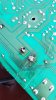
This is the entirety of the crack, it only affects one of the filter caps. The crusty stuff you see on the board there is some Gorilla glue that I've applied to both sides of the board to reinforce the crack.

Did you ever get the main filter caps out? You do know now that the big caps are usually glued to the board, right? Often, some of the other biggest of the small can caps are glued as well, and the glue is often mistaken for electrolyte leakage.
Let me ask a question not related to the damage. When you removed this board from the amp, what kind of wire connections had to be detached? Were they removable connectors? Wire-wraps? Something else?
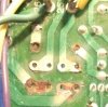
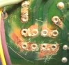
The pad on the non-damaged side appears to be completely ripped off, another thing that needs attention. The pad further to the left (and up)...the other main filter cap, looks questionable but not enough in the pic to be sure. That crack right through the main filter cap pad is definitely the most vulnerable issue, and in need of some type of reinforcement.
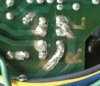
Good pic...I asked you to post it so that others could offer suggestions. Hopefully that will happen. Appears to be at least 8 cracked traces, some small, some big. You know my opinion already....i'd let it go
Let me ask a question not related to the damage. When you removed this board from the amp, what kind of wire connections had to be detached? Were they removable connectors? Wire-wraps? Something else?
The pad on the non-damaged side appears to be completely ripped off, another thing that needs attention. The pad further to the left (and up)...the other main filter cap, looks questionable but not enough in the pic to be sure. That crack right through the main filter cap pad is definitely the most vulnerable issue, and in need of some type of reinforcement.
Good pic...I asked you to post it so that others could offer suggestions. Hopefully that will happen. Appears to be at least 8 cracked traces, some small, some big. You know my opinion already....i'd let it go
Did you ever get the main filter caps out? You do know now that the big caps are usually glued to the board, right? Often, some of the other biggest of the small can caps are glued as well, and the glue is often mistaken for electrolyte leakage.
Let me ask a question not related to the damage. When you removed this board from the amp, what kind of wire connections had to be detached? Were they removable connectors? Wire-wraps? Something else?
The pad on the non-damaged side appears to be completely ripped off, another thing that needs attention. The pad further to the left (and up)...the other main filter cap, looks questionable but not enough in the pic to be sure. That crack right through the main filter cap pad is definitely the most vulnerable issue, and in need of some type of reinforcement.
Good pic...I asked you to post it so that others could offer suggestions. Hopefully that will happen. Appears to be at least 8 cracked traces, some small, some big. You know my opinion already....i'd let it go
Yes, the filter cap joints you're seeing are the joints of two brand new Nichicons. The glue is also exactly the reason why there's a crack.
 I managed to get one of the filter caps out perfectly, by gently prying it up with a blade. However, I pulled the other cap too hard and it broke off the board, taking that solder pad with it and leaving a crack in its spot.
The wires that had to be removed from the board were all wire-wrapped connections along with removable connections. I made the bonehead mistake of undoing the wraps. But luckily I have a wire wrap tool. I just have to wait for the extra wire to come in via USPS.
Did you ever get the main filter caps out? You do know now that the big caps are usually glued to the board, right? Often, some of the other biggest of the small can caps are glued as well, and the glue is often mistaken for electrolyte leakage.
Let me ask a question not related to the damage. When you removed this board from the amp, what kind of wire connections had to be detached? Were they removable connectors? Wire-wraps? Something else?
The pad on the non-damaged side appears to be completely ripped off, another thing that needs attention. The pad further to the left (and up)...the other main filter cap, looks questionable but not enough in the pic to be sure. That crack right through the main filter cap pad is definitely the most vulnerable issue, and in need of some type of reinforcement.
Good pic...I asked you to post it so that others could offer suggestions. Hopefully that will happen. Appears to be at least 8 cracked traces, some small, some big. You know my opinion already....i'd let it go
Also, what would you suggest using as reinforcement?
I wouldn't do this repair myself. Bare solid copper wire, I would guess 20ga, soldered directly to the tracks would be my first thought. Tracks scraped to clean copper, tracks tinned, wire tinned, figure some way to make the wire be in good contact throughout its contact area with the track. I would snake it along all of those larger broken tracks, a couple inches or possibly more in some spots (i.e. at least an inch on either side of each crack), and around (and in direct contact with) the pins of the main filter caps.. That would add some (perhaps not enough, IDK) structural strength. Lotta heat, big chisel iron tip (don't forget the additional flux)...definitely not Soldering 101 type of stuff.The only ones I would do point-to-point, as has been suggested, are those three smaller ones. If you can find another way to structurally reinforce the cracked area of the PCB that would also be good...I don't have any ideas on that. But again...I wouldn't even do this repair...even though I probably could pull it off. Not worth it for a $50 machine. And if doing it for learning...there are more appropriate skill sets to learn at this point IMO.
No offense...those solder joints are, to use your own words...god awful. And bearing in mind that this is where your current soldering ability lies...I suggest not doing this. Learn to solder doing baby steps, building up to replacing through-hole components into intact pads, i.e. normal stuff. You are wanting to do directly from zero to hero. And that is OK, I admire your spunk. And you do seem very intelligent and are a good communicator....points in your favor for sure.
I hope you will see some suggestions from some of the other guys. If you proceed...it will be a learning experience whether you succeed or not. LOL... I am going to step back and hope that you get some additional suggestions....
Good luck and enjoy the music
No offense...those solder joints are, to use your own words...god awful. And bearing in mind that this is where your current soldering ability lies...I suggest not doing this. Learn to solder doing baby steps, building up to replacing through-hole components into intact pads, i.e. normal stuff. You are wanting to do directly from zero to hero. And that is OK, I admire your spunk. And you do seem very intelligent and are a good communicator....points in your favor for sure.
I hope you will see some suggestions from some of the other guys. If you proceed...it will be a learning experience whether you succeed or not. LOL... I am going to step back and hope that you get some additional suggestions....
Good luck and enjoy the music
Last edited:
Hey Saffire, you have a $27 amp, dive in face first. I buy stuff like that, especially non working, just for the experience. I had a Pioneer SA-610 that the tone controls didn’t work on. Looking at the schematic, I determined there were complete separate eq circuits for each left and right ch. The problem was affecting both ch’s. The only things that were common to both left and right was a tone defeat switch. I did a continuity test across the tone switch terminals and it was good. I started tracing back from the switch and I soon noticed I had a broken connection between it and another component. It was very difficult to see, but the board had a crack that isolated that switch. I took some wire, maybe 22ga, and stripped enough insulation to solder each broken trace. I didn’t try to repair the trace, but rather soldered one end to the switch terminal and the other to the solder pad of the next component along the trace. I think I did three or four wires and it was back in working order. That amplifier was pretty rough and I am sure it was dropped on the switch. I paid <$20 for it just to work on it. I think it was good practice for the next thing that came along, and so on.
I would suggest getting some solder wick and flux for future soldering/ desoldering. Practice by removing components from old Boards and even soldering twisted wires. Keep your solder tip clean with a wet sponge and one of those bristle pad cleaners.
I would suggest getting some solder wick and flux for future soldering/ desoldering. Practice by removing components from old Boards and even soldering twisted wires. Keep your solder tip clean with a wet sponge and one of those bristle pad cleaners.

agreed, the experience gained from the repair, successful or not, will be worth more than the amp is. I learned how to fix things by breaking stuff, and I guarantee if you make no attempt at fixing anything you'll never learn how to do it. Practice makes perfect as they say, and its true. I have never met a person who made perfect solder joints the first time they tried.

merlynski
Curmudgeon Electronicist
Go for it, take your time, do clean work. The skills you gain will be your own. Remove the cap and do all the repairs before reinstalling it.
Spread the crack a bit and work some UV setting glue down into it, line it up and hit it with some UV light to catalyze it.
Use a fine abrasive to buff away the green soldermask from the traces. This will also give a good surface to tin the trace with solder, tin it lightly.
Take a piece of bare copper wire, smack it flat with a hammer on a hard smooth surface, until it is about as wide as the trace. Cut it long enough to overlap the crack in the trace about a half inch on each side. Tin both sides. Add some liquid flux on the tinned trace. Lay the flattened wire on the trace. Hold down one side with a toothpick (or similar) and gently run the iron along the wire so the solder flows and sticks the wire to the trace, starting by the crack and moving away. Let it cool a bit. Move to the other side of the crack. Hold that end of the wire to the trace with a toothpick, and gently run the iron along the wire so the solder flows and sticks the wire to the trace, starting by the crack and moving away. Do the same with all the other traces. Clean off all the flux. You can get some green soldermask coating (like a paint) that will also catalyze and set with uv light to make it look better. Amazon sells soldermask in different colors, and UV flashlights. You can also buy copper tape with conductive adhesive to bridge cracks. This works great on wider traces because the tapes sticks itself to the trace, then solder the ends to the trace. Amazon carries different widths of copper tape, from 1/8"(3mm) to 3". You can trim it with a sharp blade to match curves and irregular edges.
(I have no Affiliation with Amazon except as a customer)
Spread the crack a bit and work some UV setting glue down into it, line it up and hit it with some UV light to catalyze it.
Use a fine abrasive to buff away the green soldermask from the traces. This will also give a good surface to tin the trace with solder, tin it lightly.
Take a piece of bare copper wire, smack it flat with a hammer on a hard smooth surface, until it is about as wide as the trace. Cut it long enough to overlap the crack in the trace about a half inch on each side. Tin both sides. Add some liquid flux on the tinned trace. Lay the flattened wire on the trace. Hold down one side with a toothpick (or similar) and gently run the iron along the wire so the solder flows and sticks the wire to the trace, starting by the crack and moving away. Let it cool a bit. Move to the other side of the crack. Hold that end of the wire to the trace with a toothpick, and gently run the iron along the wire so the solder flows and sticks the wire to the trace, starting by the crack and moving away. Do the same with all the other traces. Clean off all the flux. You can get some green soldermask coating (like a paint) that will also catalyze and set with uv light to make it look better. Amazon sells soldermask in different colors, and UV flashlights. You can also buy copper tape with conductive adhesive to bridge cracks. This works great on wider traces because the tapes sticks itself to the trace, then solder the ends to the trace. Amazon carries different widths of copper tape, from 1/8"(3mm) to 3". You can trim it with a sharp blade to match curves and irregular edges.
(I have no Affiliation with Amazon except as a customer)
Last edited:
Go for it, take your time, do clean work. The skills you gain will be your own. Remove the cap and do all the repairs before reinstalling it.
Spread the crack a bit and work some UV setting glue down into it, line it up and hit it with some UV light to catalyze it.
Use a fine abrasive to buff away the green soldermask from the traces. This will also give a good surface to tin the trace with solder, tin it lightly.
Take a piece of bare copper wire, smack it flat with a hammer on a hard smooth surface, until it is about as wide as the trace. Cut it long enough to overlap the crack in the trace about a half inch on each side. Tin both sides. Add some liquid flux on the tinned trace. Lay the flattened wire on the trace. Hold down one side with a toothpick (or similar) and gently run the iron along the wire so the solder flows and sticks the wire to the trace, starting by the crack and moving away. Let it cool a bit. Move to the other side of the crack. Hold that end of the wire to the trace with a toothpick, and gently run the iron along the wire so the solder flows and sticks the wire to the trace, starting by the crack and moving away. Do the same with all the other traces. Clean off all the flux. You can get some green soldermask coating (like a paint) that will also catalyze and set with uv light to make it look better. Amazon sells soldermask in different colors, and UV flashlights. You can also buy copper tape with conductive adhesive to bridge cracks. This works great on wider traces because the tapes sticks itself to the trace, then solder the ends to the trace. Amazon carries different widths of copper tape, from 1/8"(3mm) to 3". You can trim it with a sharp blade to match curves and irregular edges.
(I have no Affiliation with Amazon except as a customer)
That's all great advice, thanks! I'll be getting started on the project tomorrow. I've been taking the time to brush up on my soldering skills.
One question, though. Since this is the power board I'm working on, would it be alright if I just ran jumper wires from one solder joint to the other on all the traces? I feel like that would be the most stable connection that's guaranteed to last, compared to scraping the traces and creating makeshift solder joints.
merlynski
Curmudgeon Electronicist
That would not be a problem unless you used too skinny a wire. Sometimes routing of traces is chosen for noise reduction. Run the wires along the traces and glue them down in spots to keep them in place. Large areas of copper are also, sometimes, used for shielding and as heatsinks. Without access to the design engineers' thinking it may be impossible to know.
Noise and ripple current handling (including wire routing) is more important in power supplies than most people recognize, but if your power supply is noisy, you will NEVER have a good quiet noise floor in your amp. A good power supply is the foundation of a good amp.
Noise and ripple current handling (including wire routing) is more important in power supplies than most people recognize, but if your power supply is noisy, you will NEVER have a good quiet noise floor in your amp. A good power supply is the foundation of a good amp.