• Please note that Audiokarma will be offline briefly for updates early on Monday morning, September 28th.

FM-200-B Refresh

The FM-200B is likely one of the very best FM Stereo MPX tuners ever produced back in the heyday of the Stereo/Hifi craze -- virtually as good performance wise and immanently more practical than the top of the line, but studio monitoring oriented FM-1000. It, as well as all of Fisher's products stand proud representing an era gone by, and deserve the finest effort we can give them to help preserve their mark on the history of high quality vacuum tube sound reproduction.

Dave

Dave,
Not to derail this thread, but I'd be interested in your opinion on two questions about the FM-200 series.

First, is most of your technical information here applicable to the mono FM-200?

Second, which tuner do you feel is superior? The mono FM-200 with the MPX-100 attached, or the integrated FM-200B?
 
Hi Sam -- You know, I've never seen (or have been able to find) the schematic of an FM-200, but I have seen them for sale at auction, and they would appear to have the same performance capabilities in tuner section as the 200B does, with the biggest difference that the B uses Nuvistors in the front end, where as the non B uses traditional RF dual triodes.

That really does not give the B a performance advantage, but is more in keeping with Avery's desire to be the first if at all possible, with any electronic advances. When Nuvistors became available, they were integrated into the design when changing to the B, to keep the image of his company as one of being on the cutting edge. In reality however, the practical advantage of using Nuvistors is only apparent at much higher frequencies than the FM band represents. Therefore, from tuner performance standpoint, the 200 and 200B should for all intents and purposes be nearly identical.

On the MPX side of the equation, the MPX sub-chassis in the B, which is of the time division design, versus the design of the MPX 100 (based on the design as shown in the service manual in the digital docs), which is a matrix only design, is notably superior. Therefore, I would have to give a decided edge to the 200B, over that of using a 200 using an MPX 100 for stereo decoding. IIRC however, the design of the MPX 100 changed significantly at some point in it's production run, so my comments here should be understood as being based on the early production runs of that unit.

Dave
 
My MPX-100 is one of the later iterations. I've seen evidence of at least four, though I don't have all of the service manuals - and in fact don't have one for my particular version of the 100, which, I think, was the final design.
 
Boy, it would be great if one could surface. The one in the digital docs is for the very earliest units. I have no doubt that that unit went through substantial design changes throughout its production run. MPX decoder design was advancing and changing rapidly in the early years of FM MPX Stereo -- precisely when the universal decoders were being offered.

Dave
 
My MPX-100 is one of the later iterations. I've seen evidence of at least four, though I don't have all of the service manuals - and in fact don't have one for my particular version of the 100, which, I think, was the final design.

Sam; I have copies of the 10001-19999, 20001-39999 and 40001-49999 and the Sam's for the 1st one. PM me your Email address and I'll send ya the PKG.

DAVE: You should have it already. I sent it a few minutes ago.

Larry
 
Whoa yeah -- starting with the units of serial number 20001 and up, the MPX 100 converted to using a somewhat more complicated, but basically topologically identical time division design, similar to that used in the sub-chassis units.

As long as the MPX interconnect is kept short, then the FM 200 and the later MPX 100 decoder should perform identically with the FM 200B. In that case then, the 200B just represents a nice, complete package, rather than the separate units that the 200 requires.

Dave
 
Sam; I have copies of the 10001-19999, 20001-39999 and 40001-49999 and the Sam's for the 1st one. PM me your Email address and I'll send ya the PKG.

DAVE: You should have it already. I sent it a few minutes ago.

Larry

Thanks!

Just checked mine, it's #219xx. I know the tube compliment and overall circuit is radically different than the early version. Even the tube layout on the chassis is quite different. Small running changes I can understand, but I really don't know why they didn't give the later versions 'B' and 'C' designations to more clearly pick out that they'd made significant alterations.

I do know that it sounds very good connected to the FM-200. I've never had the opportunity to compare them with an FM-200-B.
 
Sam; Just sent you all of them. (Including the Sam's for the 10001-19999 version). I've got to pull mine out, but IIRC it's the latest iteration. It needs to see Dave one of these days. I've also got a Sherwood A3mx and it's got really nice separation.


Larry
 
Just curious if Nuvistors are easy, or hard to come by these days. I'm guessing harder than a normal Valve. I remember a British company, Musical Fidelity, putting NOS ones in their modern components and including spares for each one.
 
They are out there, had to get one replaced that was shipped poorly, its on the way to Ga as we speak. You guys with 500c's have 2 of them in yours as well. Never knew that till Dave pointed it out. My 800C does not have them...:scratch2:
 
I was able to get several 6CW4s (RCA) for the Fisher 600-T restoration project from eBay but I'm not real sure if they were new as advertised. There is a point on the IF board where a measured voltage is dependent on current draw of the oscillator tube and none of my tubes actually made it to that voltage. Meanwhile, there is oscillator drift of maybe 200-300 kHz for the first 10 minutes. I don't remember that happening on a new unit.
 
Waiting......and Odds and Ends

After the recap, the tuner was put back into service, with a few details noted to take care of:

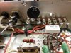
1. The additional B+ dropping resistor took care of the vast majority of over voltage produced by the silicon rectifier, but it was noted that both the B+ and heater voltages were still on the high side with a 121 vac line, with the heaters being nearly 10% so. The addition of a CL-90 brought the heaters to within +4% of target, and the B+ within +4 vdc of target. This is particularly important for tuners, as one of the all-to-typical problems that develops within the tube types that are used in tuners is heater/cathode leakage or shorts. That conditions will often disqualify a tube before poor Gm performance does -- and high heater voltage only serves to accentuate the possibility that leakage will occur. Keeping the heater voltage within 5% of target will help ensure maximum life from tuner tubes.

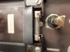
2. Some techs don't realize what fanatics we Fisher fans are! This unit had the typical 8 volt Fuse Style bulbs SOLDERED in place for the dial lamps, because someone along the way apparently used the fatter festoon lamps in this unit than were called for, which broke out (or required the breaking out of) the dial glass side of the lamp well to accommodate them. This ruined the four sockets, and meant that the proper festoon lamp, or even the Fuse Style lamps would no longer snap and hold in place, requiring the previous tech to solder in the existing fuse bulbs. It works, but is hardly convenient when change out time comes.

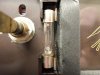
Different options were examined to try and fix the broken out sides of the socket wells to have them work as Fisher intended them to, but all were involved, and hardly left a stock look to the fix. At that point I realized that by disconnecting and removing the clip from each well, and simply reversing them -- so that they clamped the bulb between the clip and the remaining in tact side the lamp well, a fix could be had with no one really the wiser about it. It worked perfectly!

3. This unit also suffered from a Muting indicator lamp that was well, flaky. Turn on the Muting function, and maybe the light would come on, maybe it wouldn't, but usually it would wink at you -- although you were never really sure just what it was going to do.

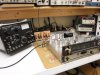
That was traced to the switch on the control, and while a replacement has been found, it still has yet to be delivered. And so we wait........

In the mean time however, the rest of the tubes came in, so with hot tubes in all sockets, the alignment could be checked even with the Muting control removed from the unit. I use a Sound Technology 1000A for the tuner circuits, but still prefer to use The Fisher 300 Multiplex Generator for the MPX work, not only for sentimental reasons, but because it is a superb piece of equipment in its own right as well. For the tuner circuits however, the 1000A is unsurpassed in the quality of alignment it can provide for, and the time involved to achieve that end.

Once touched up, this particular unit achieved 20 db of quieting with a signal level of just 1.25 uV which is quite remarkable. For those with owner's manuals for the 200B, you might note that the spec for 20 db of quieting is a signal level of just 1 uV........

We are all very familiar with the power rating wars, and in how the manufacturers all got caught up in trying to spec that the unit they offered had more power than a competing unit -- when in fact it may have had less! Even Fisher was caught up in this to some degree -- but only slightly compared to the degree that some manufacturers were. Well guess what? The same game went on in the tuner business as well with sensitivity figures.

Most quality tuners of the day will have a specified sensitivity rating (for 20 db of quieting) under 2 uV, but only the best ones will achieve that performance level. In my experience, the better Fisher tuners will always be under a 2 uV level, and often around the 1.5-1.6 uV range. So for this bad boy to clock 1.25 uV is something special indeed. By comparison, when the original tubes were reinstalled, 20 db of quieting required nearly 3 uV -- due primarily to a weak Nuvistor mixer tube, but also to an IF strip that needed touching up.

Once the Muting Control switch arrives, this project will be a quick wrap up, since everything else ready to go. Like the X-202B amplifier, the FM-200B is Fisher's best and most practical tuner, that will really make the best modern tuners have to work for their supper!

Pics include:

1. Just one solder connection left to go. After installation, the CL-90 brought all the voltages nicely within range now. The T-Strip for it is mounted in the other mounting hole accommodating some of the old selenium rectifier packs.

2. The lamps were originally soldered in place due to the broken out sides of the lamp wells which can clearly be seen in this pic.......

3. But now can easily be snapped in and out as needed.

4. Waiting for the new Muting Switch to arrive is like waiting for a pot of water to boil........

5. When the RF level control on the 1000A was increased to achieve 20 db of quieting, the control landed on 1.25 db -- once again showing why Fisher Tuners were arguably some of the very best in the business.

Dave
 

Attachments

  • SAM_1150.jpg
    SAM_1150.jpg
    89.1 KB · Views: 87
  • SAM_1148.jpg
    SAM_1148.jpg
    66.6 KB · Views: 93
  • SAM_1149.jpg
    SAM_1149.jpg
    66.2 KB · Views: 94
  • SAM_1151.jpg
    SAM_1151.jpg
    109.1 KB · Views: 82
  • SAM_1152.jpg
    SAM_1152.jpg
    84 KB · Views: 80
Last edited:
Looking great Dave, this Tuner will be set for life now, great work! Al PS Thanks for the pic of the CL 90... now I know what it is. :)
 
Last edited:
Wow, Dave! Fantastic work. Very clever how you reversed the clips on the lamp wells. I've been testing a lot of 6AU6s lately, and quite a few have shorts... wonder if that might be a result of higher household voltages since the time these old guys were manufactured?
 
Absolutely, and was exactly my point, which is why I made an adjustment to the effective line voltage applied to the power transformer by way of adding the CL-90. The small signal HF pentodes work hard, and get really hot under those tube shields (so do the RF tubes as well). Adding extra heat due to high line voltages can really stress the heater/cathode insulation in the tubes, and cause the leakage to occur.

Dave
 
The fuse holder looks like it could use some more heat on the tip and solder on the one wire maybe?

On mine I put in LED's for the lamps. But do like how you did yours out of necessity.


Barney
 
Absolutely correct Barney -- in fact, that connection hadn't even been soldered yet! The pic was taken before that last connection was soldered, with the comment for that pic being "just one solder connection left to go.......

I've used and like the LEDs as well, which tend to give a more modern look. There are also folks who like the warmer look of the original incandescent bulbs, too. Both look very good to me, with each having their own individual preference.

Dave
 
After the recap, the tuner was put back into service, with a few details noted to take care of:


3. This unit also suffered from a Muting indicator lamp that was well, flaky. Turn on the Muting function, and maybe the light would come on, maybe it wouldn't, but usually it would wink at you -- although you were never really sure just what it was going to do.

That was traced to the switch on the control, and while a replacement has been found, it still has yet to be delivered. And so we wait........

Dave

What a timely post: just this weekend I had hooked up my own tuner for a healthy trial run. No major complaints except for those indicator lights! My muting light does NOT turn off, and the middle light (I assume a power indicator light) doesn't turn on. I was enjoying the music too much to be bothered by the quirk but now that you've identified at least one possible cause I'll look into it with the hope off correcting it.
 
Back
Top Bottom