Audio and MPX Circuits
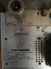
In the underside pic of the unit as originally received, you can see the two output coupling caps used to block the DC at the output of the cathode follower outputs from the output jacks in the lower left corner of the pic. Not the easiest caps to get at and remove, particularly if you remove their compete leads rather than just snip them out. But, they should certainly be replaced in any full refurbishment.
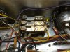
Ditto for the MPX subchassis. The 1 uF composite signal electrolytic coupling cap always gets the proper attention to be replaced (as it did from the previous tech), but the pilot signal coupling cap and audio output coupling caps rarely get any mention, let alone replacement. But these caps are of the same kind that get loudly decried to be replaced in the general audio circuits, and with good reason. They don't often develop any leakage (although they can), but you can bet they will eventually become intermittent. Therefore, these caps too should be replaced with any full refurbishment effort. Also not the easiest to get to to replace with a neat, finished appearance, but well worth the effort in terms of long term dependability.
So, all the old film coupling caps have been replaced in both of these areas now. With that and the power supply circuits finished, all that remains then are about a half dozen caps in the Auto Stereo and Microtune control circuits. A complete alignment check will top off the project after all the work is complete.
But, with the parts in now for the buffer circuit of the X-202B project, it will move back to center stage for the moment to keep it on track. A few pics show the progress:
1. The finished audio circuits.
2. The MPX circuits showing the 3 caps to be replaced.
3. The new pilot signal coupling cap.
4. The new L & R audio output coupling caps.
5. The finished MPX section.
Back when there's more to report.
Dave