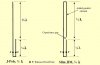
J-Pole antennae work OK as a transmitting antenna.
The same rules apply, good RF decoupling, and correct dimensions and construction for the best performance.
I used a double set of decoupling radials similar to the picture below. This helps to insure a consistent radiation pattern. Also it is possible to tilt the radiation pattern down a small amount (lower the radiation angle).
In general, if a J-Pole antenna is used for a VHF or UHF transmitting antenna, the closer to horizontal the major lobe of radiation is the better.
This is why some prefer the
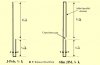
"Slim Jim" version of the J-Pole antenna.
Then there is the collinear or
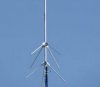
"Super J-Pole" antenna, that when designed and constructed correctly will exhibit some gain (not quite 2 dB) relative to the standard J-Pole antenna, as shown in the second picture.
There are improvements that can be applied to this antenna, such as replacing the horizontal phasing element with a correctly designed phasing coil. This will increase the gain by almost another dB, approaching a total gain relative to the standard J-Pole antenna of just a little less than 3 dB.
Again, I will recommend
4nec2 antenna modeling software for those that have an interest in antenna design.
Some
screen shots of the output of this software.
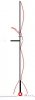
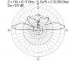
The last 2 pictures are rough examples of the output of antenna modeling software when applied to a J-Pole antenna. The third picture is the current distribution on a J-Pole antenna and the next picture is the radiation pattern for a J-pole antenna.
The feed point impedance can be improved, this is just a rough example.
And the last picture is a reminder of the "Slim Jim" version of the J-pole antenna.