• The move to the new server is done. There are some software and database maintenance updates in process. This has us passing the hat around to help out. We appreciate any donations. Seriously, even a dollar helps. The payment page may be found here - https://www.audiokarma.org/support.html

Gibson GA-50T Tube Amp What to Replace Debate...

@EastPoint @gadget73. Thank you for clarifying. The more I think about this, there is no "vintage" sound for this one because it is a jumble of parts from different eras anyway. I'd originally noted this is most of the tubes are original except the mismatched output tubes, by manufacturer not by type.

Still need to trace the part paths to see what I really have "under the hood" before I start swapping parts out.
 
Mod questions on going all in ...
  1. When I go to replace wires, is there any reason to use shielded line like in the center section repair previously mentioned in #6 above, or will simple plastic sheathed wire do? I don't know how sensitive these are to field coupling.
  2. Any reason not to replace with grounded 3-wire plug? The original power wire + plug is two-prong + ground wire alligator clip. The alligator ground wire was clipped or separated at the plug. Still with the unit, just not attached. I am not aware of a reason but figured to ask because ground design can have implications to circuit operation.
  3. A Desktop Reference of Hip Vintage Guitar Amps by Weber on pg 117 indicates the old Jensen speakers have dropped voice coils due to the animal glue deteriorating over time. Anyone encountered this? It triggers the P12R not available alternate debate, but I know this thing made sound when it was previously plugged in so this is more a curiosity right now.
 
Like for like replacement is generally fine for wires, but honestly unless they are going sticky or showing some other sign of failure I tend to leave that stuff be. Some of the plasticizers from this era do fail though and if the wire is gummy it needs to go. A sharp vinegar smell is another clue the plastic is failing. Mind the voltage rating, you probably want 600v wire for at least some of this.

If you have hum problems, a shielded wire from the input jack to wherever it goes might make sense, but most of the time you can just twist the signal and ground wire and have it behave. If the heater wiring isn't currently twisted, do that. It helps with noise.

Run the ground, you're connected to the thing by the guitar in your hand.

don't know on the speaker but if it seems to be in good working shape I wouldn't worry too much about it. Hide glue does fail with moisture but its also not that big of a deal to repair if that happens. Not sure if they used hide glue on paper cones or not, won't pretend to be a vintage speaker expert but I've worked on a lot of old crap and never had a speaker that had the voice coil or cone separate from glue failure.
 
I don't see why you couldn't use shielded wire to connect to the controls if the wires are noisy.
There isn't any reason not to add an earth ground. I have found adding an earth ground to a couple older pieces of equipment that didn't originally have one caused a hum. It's easily removed if that becomes an issue.
For speaker drivers thst are known to have the magnets shift I put a few beads of epoxy around the magnet where it meets the basket. With Alinco magnets you can add another few beads of epoxy at the other end.
 
if its the magnet that comes off I doubt that would have been done with hide glue originally. Not really sure what the metal to metal bond would have been back then.
 
I've found the older Polk speakers around the time the Monitor series came out used a glue that didn't hold up very well along with some earlier to mid 70's Realiatic speakers. One good bump and the magnets shift. I'm sure there are others that have this problem as well. Using some epoxy or some other glue around the magnets keeps them in place. I haven't ever heard that hide glue was uses though.
 
I don't see why you couldn't use shielded wire to connect to the controls if the wires are noisy.
There isn't any reason not to add an earth ground. I have found adding an earth ground to a couple older pieces of equipment that didn't originally have one caused a hum. It's easily removed if that becomes an issue.
For speaker drivers thst are known to have the magnets shift I put a few beads of epoxy around the magnet where it meets the basket. With Alinco magnets you can add another few beads of epoxy at the other end.
JB Weld, if you worry about road shaking and damage to the speakers.
 
Last week I finally got around to ordering parts for a full rebuild. I decided to trust it and play it the rebuild was necessary. I'll label and catalog the existing parts for whoever gets this in the long distant future, but I decided play ability was more important than originality (which was suspect anyway).

modifications I'll likely add backup rectifier diodes for protection, and I'm debating whether to put a 90% attenuation switch on the output with the high watt resistors mounted on a new metal plate heatsink that uses existing holes so the mod can be reverted by desoldering. I'm just playing at home so I suspect I'll like the attenuation switch addition.

Question on cathode bypass capacitance
I decided to not go stupid large, like current 150/100 uF Mallory can, and instead use 2 JJ Electronics 40/20/20/20 uF combo-caps to cover the 40 uF, 4 x 20 uF, and 3 x 10 uF circuit specification. I have questions on how to allocate it though.
  1. Does anyone know if the combo capacitor cans have cross-talk issues that would mean I wouldn't want to mix signal and power duties?
    1. this assumes cathode bias locations impact signal more than power input stage filtering/reservoir
  2. Am I better doubling the output stage cathode bias cap from 20 uF to 40 uF or leaving it at 20 and increasing the 20 uF off the heater circuit transformer to 40?
Note: part of the reason to back away from massive multiplier of the cap values is to allow circuit to reduce bass a little, rather than pushing it all to the ancient woofers.
 
9a64e63d-748c-4124-8fb7-008a375713af.jpg

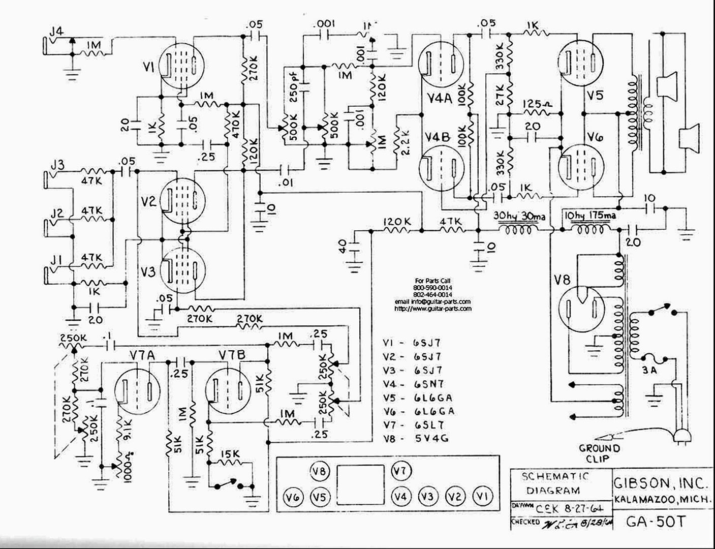
Here's a schematic (I believe) for your amp. Specifically, which bypass caps are we talking about?

Thanks!

b68d9dd3-665d-428b-83f9-aa412ce4000b.jpg

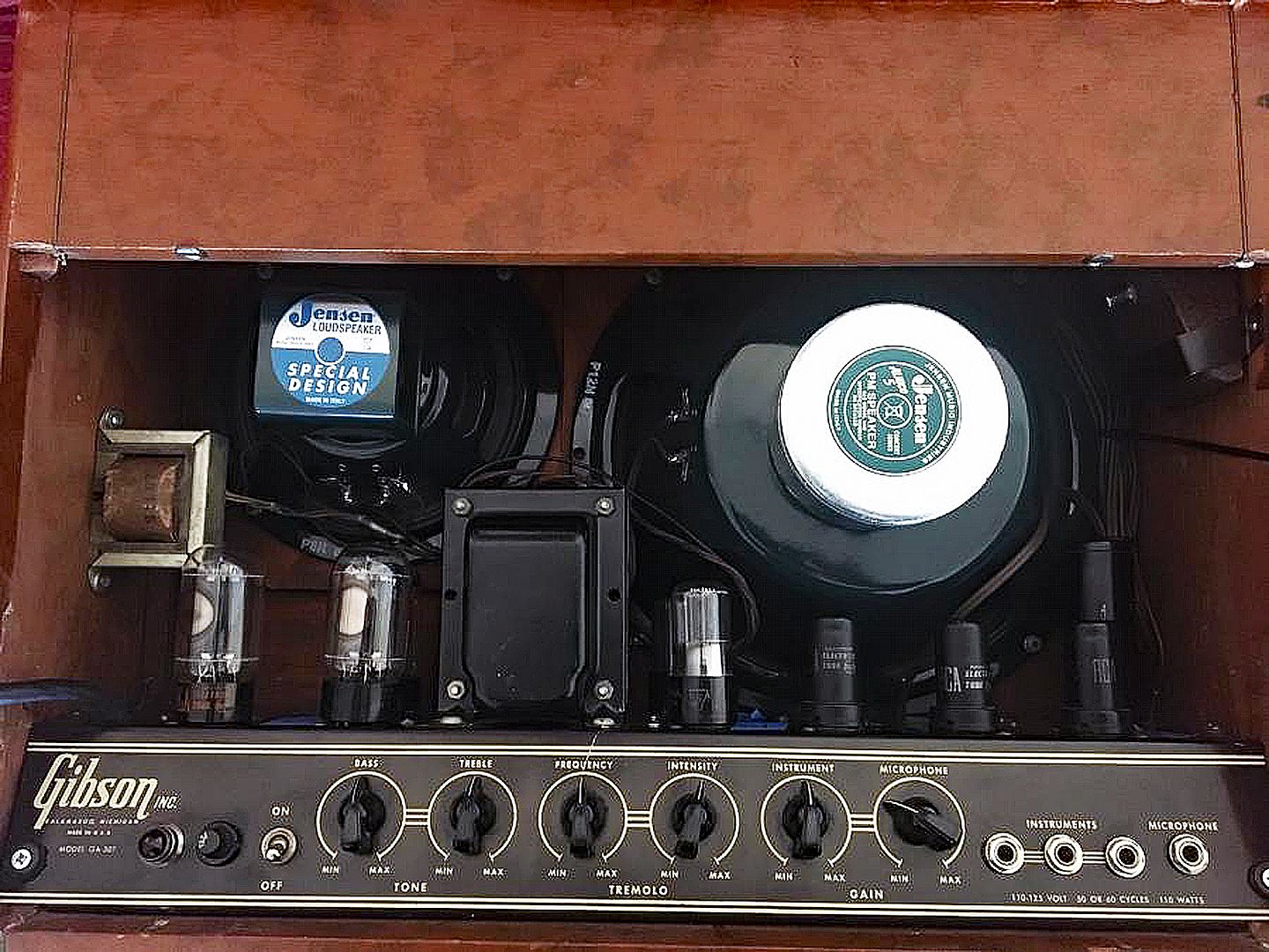
Photo of the control panel and inputs.
 
Last edited:
No issues with cross-talk within the can caps. It was very common for multi-caps to have several high voltage sections for the power supply, and a low voltage section for the cathode cap.

No real reason to make that cathode cap bigger either. Sometimes if you do that it can cause stability problems, so I'd be careful about changing values by large amounts. Within 20% is pretty safe but doubling things may not be so good. If you absolutely have to trade a 20 for a 40 though, the cathode cap being larger is less likely to have issues. The rectifier tube is not going to like working into a 40uf cap. A 20uf is quite possibly already larger than ideal.
 
No issues with cross-talk within the can caps. It was very common for multi-caps to have several high voltage sections for the power supply, and a low voltage section for the cathode cap.

No real reason to make that cathode cap bigger either. Sometimes if you do that it can cause stability problems, so I'd be careful about changing values by large amounts. Within 20% is pretty safe but doubling things may not be so good. If you absolutely have to trade a 20 for a 40 though, the cathode cap being larger is less likely to have issues. The rectifier tube is not going to like working into a 40uf cap. A 20uf is quite possibly already larger than ideal.
:thumbsup: 100% :thumbsup:

Some bypass cap changes may be for circuit parts that are not being used, like the mic input.

I would not change the bypass cap value in the Tremolo/Vibrato section. That can definitely lead to instabilities. This amp has a nice tube-driven oscillation circuit. These have such an excellent, deep, natural tone. And a good 6SL7GT is going to make that sound superb. I would not mess with any component value changes in the trem part. Go with good poly coupling caps if you wish. Keep the same values.

If you keep the 6L6GA tubes, keep the 20mfd bypass cap. Increasing the capacitance may cause problems with little benefit.

I'm up with replacing the power supply capacitors and any carbon comp resistors in the power line (use new metal oxide, same values). Ramp up the voltage and see how it sounds. This is a GREAT amp; PLEASE do not go far from the OEM specs.

keu8aijpyv1mm4lgvnm4.jpg


1949 Gibson GA-50T.
 
Last edited:
I don't really work on musical instrument amplifiers, but one day, an automotive customer of mine insisted I fix his fender Bassman. He insists he wants to keep it forever and pass it on to his kid and all that hogwash...
OK, but I'm doing it my way.

Cool that's why I brought it to you...

Called him up a few days later.
Every plate resistor in this thing is over value and microphone, the board is deteriorating and I have zero confidence in my ability to rework the original board so I'm putting in a FR4 fiberglass board and populating it with Mallory film caps and Dale CMF60s and it will be a much better amplifier as a result.

Did that, cleaned the Controls and the jacks and gave him back a bassman that was nearly dead silent until you plucked a string and which delivered earth shaking power when you did so.

Charged him virtually nothing...

Next time I saw him I asked "how do you like playing that amp?"
Thinking to myself, "he has got one hell if a bass amplifier, i hope he appreciates what i did for him..."

"OH I sold it"

If you want it to work perfectly long term, gut it for a full restore. If you want some tone drunk collector to pay top dollar, sell it as it is...
In my opinion tube amplifiers are to be used, and in order to safely do so they must be overhauled, preferably 100% overhauled.
 
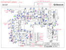
Appreciate the responses. I should have posted the component mark up that I've been using for awhile. See image below.

@Mr Boochie/@gadget73 - see below green label marks for the different large value capacitors. I was trying to describe the difference between:
  1. change C25 rectifier input in power section to 40; change C24 and C23 in power to 20, change C7 to 20
    1. this means 1 of the 40 uF caps in a 40/20/20/20 can must share with C1, C3, C21 20 uF sections
  2. split power and "signal" multi-caps
    1. C22 as 40 and C23, C24, C25 as 20
    2. C21 as 40 (changed from 20), C3, C7 and C1 as 20
  3. in both cases C7, C23, C24 go from 10 to 20 uF.
  4. @gadget73 - appreciate the response confirming no cross talk so the choice is about circuit fit not cross-talk. I had wanted to use the multi-cans to clear up space in the amp, and admittedly to minimize cost vs individual separate electrolytics.
@gadget73 Curious why you are concern about doubling the value, either on rectifier input or cathode. I've read numerous locations recommending much larger increases up to 100 uF or more safely for the cathode in particular. The amp was working (though I didn't trust it) when I started disassembly, based on those much larger caps. Are you saying the rectifier wouldn't like the inrush current?

@trainbuffton - sometimes other people suck and don't understand the time/effort it takes to repair something right.

Trying to do a quality rebuild. This one is for me, learning tubes as I go. I plan to do a full write up in git like I did with a prior Sansui rebuild. Just haven't gotten to publishing the documentation yet. These are the types of parts I bought:
  • Mostly Mojotone polypropylene caps, switched .25 to .27 Solen polypropylene because can't find 0.25 uF and it was a smaller % change than going to 0.22 uF, and metal film resistors. I may leave those 2 0.25 uF cans in but for now I assumed they'd measure bad when I pulled them out of the circuit.
  • I mostly went with JJ tubes to replace the working but mismatched set of tubes I started with.
    • Because the inputs 6SJ7 are known to be microphone with no modern replacement I ordered an assortment of NOS 6SJ7/GT and alternatives for backups.
    • I went with matched 6L6GC matched output tubes.
    • I considered the 6SL7GT because thetubestore reviews said the 6SL7 was notchy, but everyone at tubesandmore seemed to like it so figured for the cost difference and avoiding Russian Tung Sol funding I'd try it. I'll upgrade if I don't like it.

guitar.amp.gibson_ga-50t.schematic-bom_annotated_components-big_caps_marked.png
 
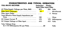
Specific to the rectifier, the larger the capacitor directly off the rectifier, the more inrush current the rectifier has to deal with, especially at power-up. Exceed those ratings and the rectifier will die a premature death. Here is a snippet from the tube datasheet for typical conditions. This isn't an iron-clad limit on cap size, but its usually not way off the mark. The cap value can bump with lower voltage or higher plate supply impedance.

1737074546848.png

If its already 20, I really wouldn't think its a great idea to use a 40 here.

You can generally bump caps after the first resistor or choke without causing problems but that first cap does have a practical limit if you don't want to feed your amplifier rectifiers like they are candy. Yes people sometimes install massive capacitors in the power supply, but it doesn't always mean they know what they are doing or aren't creating new problems.


as for the cathode cap, making that bigger will increase gain at low frequencies. Sometimes that causes no harm at all, sometimes it can cause low frequency stability problems. That would sound like extra flabby bass, or you might hear or see the speaker cone "breathing" a bit as the amp very mildly oscillates at a low frequency. Being a non-feedback amp its probably not going to cause you any grief but feedback amps sometimes have problems with this.
 
Appreciate the responses. I should have posted the component mark up that I've been using for awhile. See image below.

@Mr Boochie/@gadget73 - see below green label marks for the different large value capacitors. I was trying to describe the difference between
Trying to do a quality rebuild. This one is for me, learning tubes as I go. I plan to do a full write up in git like I did with a prior Sansui rebuild. Just haven't gotten to publishing the documentation yet. These are the types of parts I bought:
  • Mostly Mojotone polypropylene caps, switched .25 to .27 Solen polypropylene because can't find 0.25 uF and it was a smaller % change than going to 0.22 uF, and metal film resistors. I may leave those 2 0.25 uF cans in but for now I assumed they'd measure bad when I pulled them out of the circuit.
  • I mostly went with JJ tubes to replace the working but mismatched set of tubes I started with.
    • Because the inputs 6SJ7 are known to be microphone with no modern replacement I ordered an assortment of NOS 6SJ7/GT and alternatives for backups.
    • I went with matched 6L6GC matched output tubes.
    • I considered the 6SL7GT because thetubestore reviews said the 6SL7 was notchy, but everyone at tubesandmore seemed to like it so figured for the cost difference and avoiding Russian Tung Sol funding I'd try it. I'll upgrade if I don't like it.
You will find out how the bypass cap changes the tone once you try the amp.

I'm unsure if the amp's power transformer can handle the 5U4GB; they may be better for 6L6GC use. The OEM 6L6GA does not need the current of a 6L6GC — just a thought. You may want to stick with the 6L6GA and the 5V4GA combination. My units use vintage NOS US, UK/Dutch, or Japanese-made tube rectifiers.

https://www.ebay.com/sch/i.html?_nkw=5V4GA+tube&_sacat=0&_from=R40&_trksid=p4432023.m570.l1313

I do not like the Russian-made 6SL7GT tubes. They have a harsh, dry sound. Once again, US-made NOS are still relatively cheap. TungSol (USA) is the best. Sylvania, RCA, and GEs are good, too.

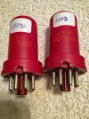
A little secret about NOS 6SJ7 tubes — think about the RCA red JAN 5693 mil-spec tubes. I used them in my old woodie-era Fender amps.

5693 6SJ7 RCA CRC.jpg

Good luck with the amp! It's a fine one, with a unique sound. The original speakers are excellent. I hope the cones are in good condition.
 
Last edited:
if you want to use some other rectifier, I'd probably go 5AR4. Same heater current draw, higher current ratings, less voltage drop. Don't really think you need it if the thing was designed for a 5V4 though.
 
if you want to use some other rectifier, I'd probably go 5AR4. Same heater current draw, higher current ratings, less voltage drop. Don't really think you need it if the thing was designed for a 5V4 though.
But it originally had 6L6G tubes, not 6L6GC. I believe the GCs have more current draw.

I don't know of any amp with push-pull 6L6GCs and a single 5V4G rectifier. :idea:
 
Back
Top Bottom