

Okay still on the slow path. I've had distractions which have prevented me from working on it for awhile. I've been building out a DIYLC Layout for the tag board I bought to try to make maintainability easier. Trying to minimize jumper paths. When I've got that done I might post it for suggestions.
Current problem
the schematic doesn't tell me how it is wired, especially not after 75 years of undocumented mods. I've been documenting connections as I disassemble in case I want to revert.
I've found an odd connection. If you look at R18, P3 in the tremolo circuit lower left it shows 9.1k R18 between one leg of 1k P3 potentiometer to V7A pin 3 cathode. Instead R18 is wired pin 3 of P3 to pin 1 of lower P1 270k pot with the P3 wiper not wired to ground but instead to V7A pin 3. Obviously there were other tremolo circuit changes but curious if anyone knows why someone might do this.
P3 is curious in general. There are only 6 knobs on the front but 7 pots. P3 is attached to the back of P1 the tremolo frequency adjustment. When I put this back together how do I know what the P3 resistor set point is? I assume it is based on oscillation harmonics but having never built (or investigated) a tremolo circuit would like guidance on figuring out how to set it before reassembly.
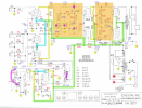
Schematic source: https://el34world.com/charts/Schematics/files/Gibson/Gibson_ga50t.pdf found on https://el34world.com/charts/Schematics/files/Gibson/Gibson_Schematics.htm. Was used to create overlay in post #55 which I've repeated here with more annotations
Current problem
the schematic doesn't tell me how it is wired, especially not after 75 years of undocumented mods. I've been documenting connections as I disassemble in case I want to revert.
I've found an odd connection. If you look at R18, P3 in the tremolo circuit lower left it shows 9.1k R18 between one leg of 1k P3 potentiometer to V7A pin 3 cathode. Instead R18 is wired pin 3 of P3 to pin 1 of lower P1 270k pot with the P3 wiper not wired to ground but instead to V7A pin 3. Obviously there were other tremolo circuit changes but curious if anyone knows why someone might do this.
P3 is curious in general. There are only 6 knobs on the front but 7 pots. P3 is attached to the back of P1 the tremolo frequency adjustment. When I put this back together how do I know what the P3 resistor set point is? I assume it is based on oscillation harmonics but having never built (or investigated) a tremolo circuit would like guidance on figuring out how to set it before reassembly.
Schematic source: https://el34world.com/charts/Schematics/files/Gibson/Gibson_ga50t.pdf found on https://el34world.com/charts/Schematics/files/Gibson/Gibson_Schematics.htm. Was used to create overlay in post #55 which I've repeated here with more annotations


