• The move to the new server is done. There are some software and database maintenance updates in process. This has us passing the hat around to help out. We appreciate any donations. Seriously, even a dollar helps. The payment page may be found here - https://www.audiokarma.org/support.html

HARMAN Kardon 930 Restoration Process

mcaddie7

Active Member
So bought a HK 930 and have been using it for several months. Given the superb shape of the thing, I wanted to make sure it would sing for another 40+ years and wanted to dip my toes in receiver restoration. I work in turntable currently but receivers are a lot more electrically technically.

IMG_9362.jpeg


I bought this recap kit from eBay: moderator edit: review the AK rules as no links to eBay auctions allowed.
The guy who owns HiFi audio is great, I’d def check out his other stuff.


So given this was my first try, I wanted to ATLEAST recap it and fix any issue I found while inside.


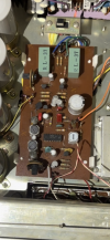
First step was to replace caps in the multiplexer board, as this feature will likely never be used again on the tuner section of this and was a good way to dip my toes into the recap.

Before:

IMG_9304.png

After:
IMG_9363.png


Turned on and she still sounded beautiful. Onto the next step!
 
Last edited by a moderator:
Register to hide this ad
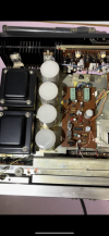
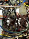
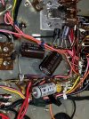
Next step was to work on the filter caps. Was slightly sad that the recap kit came with smaller foot print caps but that’s okay!

It upped the voltage as well (would be great if someone gave a brief explanation on why this is a good thing?)

Before:
IMG_9364.png

After: IMG_9349.jpeg

Not as pretty but I tried my best. I had to mount the caps somehow given that they were much smaller than the previous ones. I had soft cork that fit perfectly inside the mounting ring.

The caps had resistors across 3 out of 4 of them. When I checked the resistance they were up from 5.6k to 6.3k. My guess is that as the receiver was hot over time that they drifted.

Does anyone recommend a full resistor swap of the unit to modern ones or just the ones that drifted?

Anyways, waiting on resistors to come in, as well as thermal compound (non conductive I know) for all of the transistors as well.

Any thoughts on possibly swapping out all diodes and transistors (including output transistors) or just leave it stock?

This thread:

Makes me think it may be a good idea but given how impeccable the unit already works I’m hesitant to change too much.
 
i did some work on a 930.

i hated every minute of it.

it was a dream to listen to tho.
My issue so far has been is that everything is too well built! There's plenty of room to move around and see things. All solder points and wiring are beautifully done. My issue is that all boards come out easily, BUT, the wires soldered to them need to be removed and they are double wrapped around and through each post and then soldered. It's a pain to remove and I almost wish someone took less pride in their work when they built this lol.
 
On your question about upping the voltage rating of the capacitors, they will last longer if you run them at about 70% of their rating. So if you have 48V in a circuit, you could get away with a capacitor rated at 50V and that's what the manufacturers did a lot of times. But if you go up to a 63V or 80V cap, it should last longer. Going up too much may not be a good idea though. Electrolytic caps may not completely "form" if you don't put enough voltage through them and ESR goes up with voltage rating.
 
If it sounds good, you probably don't need to change any diodes or transistors. But you may want to check to see if you have any known troublemakers in there. https://audiokarma.org/forums/index...ilure-prone-whatever-and-replacements.731653/ Up to you if you want to replace any of them pre-emptively. If they're not known to cause problems, I wouldn't change them. Some of those old transistors are really well made and will be fine for many more years.

I don't know about the 930 but I just worked on a slightly newer HK 590i and the transistors in the phono stage have a couple dB lower noise floor than anything you can buy today so you'd rather not replace anything like that unless you have to to get it working again.
 
Last edited:
Is that cork around the filter capacitors between the clamps?
I've used foam insulation before.

Or even better get the correct size clamps and mount them.
 
Is that cork around the filter capacitors between the clamps?
I've used foam insulation before.

Or even better get the correct size clamps and mount them.
i have used speaker gasket foam before but then i started thinking about 20 years down the road when the foam dry rots and the cap falls out:eek:

now i buy the proper size or buy new clamps.

i bought some fat kemets for the 930 i did.
 
you haven't done the tone board yet have you?
Yeah that one I’m saving for last lol. What exactly is the time board used for? The caps and everything look okay so I’m assuming that if I left it be it’d be fine. However I supposed you should never leave a job half finished…..
 
Is that cork around the filter capacitors between the clamps?
I've used foam insulation before.

Or even better get the correct size clamps and mount them.
Yes! Soft cork that I cut in one piece. Looks a lot more clean in person than what you see here. Any tips for clamps?
 
If it sounds good, you probably don't need to change any diodes or transistors. But you may want to check to see if you have any known troublemakers in there. https://audiokarma.org/forums/index...ilure-prone-whatever-and-replacements.731653/ Up to you if you want to replace any of them pre-emptively. If they're not known to cause problems, I wouldn't change them. Some of those old transistors are really well made and will be fine for many more years.

I don't know about the 930 but I just worked on a slightly newer HK 590i and the transistors in the phono stage have a couple dB lower noise floor than anything you can buy today so you'd rather not replace anything like that unless you have to to get it working again.
Thank you for the info on this and the caps. I did check and no known bad transistors on this unit. Was going to go through and apparently you can roughly check each transistor while they are still soldered into the board?

It’s dead quiet when turned up load with nothing playing so I’m guessing they are all okay?

That was my thought, there will likely always be transistors (including output) that will be produced as a replacement, so just leave them be. Was thinking of adding new thermal paste to output transistors though.

What are your thoughts on upgrading all resistors to new metal film ones?
 
Thank you for the info on this and the caps. I did check and no known bad transistors on this unit. Was going to go through and apparently you can roughly check each transistor while they are still soldered into the board?

It’s dead quiet when turned up load with nothing playing so I’m guessing they are all okay?

That was my thought, there will likely always be transistors (including output) that will be produced as a replacement, so just leave them be. Was thinking of adding new thermal paste to output transistors though.

What are your thoughts on upgrading all resistors to new metal film ones?
You can check for shorted or open transistors most of the time in-circuit. If you suspect there's a problem though, it really has to come out to be tested. Even then, testing with a multimeter won't tell you if it's noisy. But if it's dead quiet turned up with no signal, you're probably in great shape.

New thermal paste is usually a good idea. You might want to have some spare mica insulators available in case you damage any. If you bend them, they can crack or separate easily and then you need to toss them.

Metal film resistors produce the least noise so if you're really chasing every last bit of performance, I suppose you could. I have done it when I had an amp with lots of carbon composition resistors that had drifted out of tolerance and needed to be replaced anyway. If yours has carbon film resistors, I doubt it'll be worth the trouble.
 
Thank you! Learn something new everyday. I won't do it right now as the cork really does like fine in person, but perhaps if I ever open it back up for parts ordering to change the lights to LED I'll do it. The resistors should be in tomorrow and I'll continue to work on recapping the other boards.
You will need the size of the capacitor then search for the proper one.

Will need to drill new holes more then likely. Did not see extra holes in picture.

Here is a link to a similar one.... https://www.digikey.com/en/products/detail/cornell-dubilier-knowles/VR10A/1933474


Update:

So after the power caps I should have plugged in the receiver but I did not.
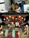
I went on to the amplifier board, as well as changed the thermal paste on all transistors on the amp, as well as this random IC pictured.


IMG_9714.JPG
IMG_9347.JPG

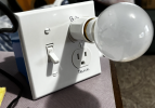
I plugged in the receiver after this step and I heard a wonder "sizzle" sound, and the receiver then powered off. I was MORTIFIED. I did some research and learned about the Dim Bulb Tester. Never too late too start learning so I let off to go build one while I thought about what I did wrong. Great guide here: Link

1713494942402.png

Next step was to recap the preamp, as well as the rest of the power caps. These were both fairly easy and I had no trouble doing this. This baord was super easy to lift up and nothing other than the caps had to soldered.

Before:
IMG_9712.JPG

After:
IMG_9713.JPG


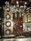
Power Caps.
Before:
IMG_9706 2-min.JPG
After:
IMG_9707.JPG


Now that all power related caps are done I need to focus on biasing the thing / adjusting DC offset. Given that there are a number of threads on this with various answers that aren't very beginer friendly I'm hoping to post another thread and get some answers which I'll link here for future use.

Later when I get the energy I'll teardown the rest of the receiver and do the tone-board as well as the other FM/AM boards.

Until next time!
 

Attachments

  • IMG_9712.JPG
    IMG_9712.JPG
    151 KB · Views: 35
Okay, So update. It really was quite the challenge to get to the tone board but we did it and only had to clip a few wires to get there. I've found that clipping the wires and resoldering them is easier on this unit. The techs that worked these wrapped the wires tightly around the pins and it's impossible to get the solder free. Anyways, the kit I bought is missing quite a few capacitors (Not impressed for 135 dollars - sigh-). So I had a question on a few parts.

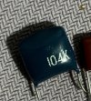
For the 2 film caps on the tone board they are blue and read 104k, what are a good replacement for these while I'm in there:
IMG_9768.JPG

Now I'm learning on this next step so bear with me. I think I'd like to replace all the smaller transistors on this toneboard given that I have it out (again it took almost an hour to safely remove it) plus I'm looking to learn about transistor replacement. To keep original sound there are three smaller transistors on this unit. Any suggestions for good, modern, perhaps better performing replacements?
1) 2SA564
2) 2SC644
3) 2SC828

I was thinking of using this website which finds direct replacements: Alltransistors.com

When choosing replacements is it best to find exact matching or improve and exceed while you're at it (like the voltages on cap replacement) .

For example, it appears these 2222A transistors I have spares of exceed the values or the 2SC644, does that mean I can use it?

Thanks for any and all help!
 
Now I'm learning on this next step so bear with me. I think I'd like to replace all the smaller transistors on this toneboard given that I have it out (again it took almost an hour to safely remove it) plus I'm looking to learn about transistor replacement. To keep original sound there are three smaller transistors on this unit. Any suggestions for good, modern, perhaps better performing replacements?
1) 2SA564
2) 2SC644
3) 2SC828

I was thinking of using this website which finds direct replacements: Alltransistors.com

When choosing replacements is it best to find exact matching or improve and exceed while you're at it (like the voltages on cap replacement) .

For example, it appears these 2222A transistors I have spares of exceed the values or the 2SC644, does that mean I can use it?

For transistors in the audio signal path, a generic 2222A would not be the best choice.

It is OK to look for a replacement transistor that "meets of exceeds all specs", but is also not the best way to go. For many reasons. To learn more, here is a start: Transistor Replacement Guide.

Better would be to search AK here to see if anyone has done similar (asked about this and gotten replies, potentially a discussion). Like https://www.audiokarma.org/forums/index.php?threads/hk-930-tech-advice.757415/

The best thing to do, however, is:

  • For a given transistor in a specific circuit, like "TR101 on the tone board in a HK 930"
  • Post here or in a new thread
  • Tell us where the transistor is going to be used (i.e. "TR101 on the tone board in a HK 930")
  • Post an image of the schematic (so those of us who don't have the service manual you're using can easily follow along and help)
  • Tell us which transistor you want to replace
  • Ask for help with that specific transistor being used in that particular spot of a specific circuit

That tells us the application of the transistor. That knowledge helps to guide us to which parameters are important, which are not, and, sometimes, which of several replacements is best for that application.

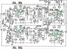
I don't see any 2sc564 on the tone board; only 2sc644 and 2sc828:
HK 950 tone board transistors.png

All of those are in the audio signal path, so you'll want to look for low noise small signal transistor replacement. Getting the specs of the original devices from alltransistors.com is a great first step.

2SC644
NPN
Power Dissipation (Pc): 0.15 W
Collector-Base Voltage |Vcb|: 25 V
Collector-Emitter Voltage |Vce|: 25 V
Emitter-Base Voltage |Veb|: 5 V
Collector Current |Ic max|: 0.05 A
Transition Frequency (ft): 75 MHz
Collector Capacitance (Cc): 10 pF
Forward Current Transfer Ratio (hFE), MIN: 350
Noise Figure, dB: not stated
Package: TO-92
Pinout: ECB

For low noise, since the above 2sc644 is low current 50mA and low voltage 25V, I'd start with looking at the KSC1845F.

KSC1845F
NPN
Collector Power Dissipation (Pc): 0.5 W (better than 2sc644)
Collector-Base Voltage |Vcb|: 120 V (better than 2sc644)
Collector-Emitter Voltage |Vce|: 120 V (better than 2sc644)
Emitter-Base Voltage |Veb|: 5 V (same as 2sc644)
Collector Current |Ic max|: 0.05 A (same as 2sc644)
Transition Frequency (ft): 50 MHz (lower than the 2sc644, but we're doing audio that only goes to 20KHz, so this is fine)
Collector Capacitance (Cc): 1.6 pF (better than 2sc644)
Forward Current Transfer Ratio (hFE), MIN: 300 (not quite as good as expected from 2sc644, but plenty fine)
Noise Figure, dB: not stated but amongst the best
Package: TO-92 (same as 2sc644)
Pinout: ECB (same as 2sc644)

All its (important to us and our application in this circuit) specs meet or exceed, it does very well as a small (audio) signal amplifier (which is what the application of the 2sc644s on the HK 930 tone board are doing), and it is ECB pinout.

2SC828
NPN
Power Dissipation (Pc): 0.25 W
Collector-Base Voltage |Vcb|: 30 V
Collector-Emitter Voltage |Vce|: 30 V
Emitter-Base Voltage |Veb|: 5 V
Collector Current |Ic max|: 0.05 A
Transition Frequency (ft): 110 MHz
Forward Current Transfer Ratio (hFE), MIN: 65
Noise Figure, dB: not stated
Package: TO-92
Pinout: ECB

Same thing here for the 2sc828: low current, low voltage, best to have low noise... so, again, the KSC1845F would be amongst the best choices.

All this said, it would also be helpful to read the first page of Noisy transistors to replace on sight as it may help you in your quest for what to replace and what to replace those with.

 
Last edited:
Back
Top Bottom