• The move to the new server is done. There are some software and database maintenance updates in process. This has us passing the hat around to help out. We appreciate any donations. Seriously, even a dollar helps. The payment page may be found here - https://www.audiokarma.org/support.html

HARMAN Kardon 930 Restoration Process

IMG_9944.jpeg

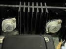
So I started my work in the output transistors. Easy enough to remove, just undo the two screws holding it in place and gently wiggle out.

IMG_9946.jpeg

From there used alcohol to clean it up, it was basically bone dry so not good heat transfer! I treated this like I treat CPUs in computers but if someone has opinions I’m down to learn. Wanted to make this a complete guide for the HK930.

Applied pea sized drop and reinserted after cleaning contact pins.

Tonight I replace all transistors on Amp board, add a variable resistor for the 330ohm resistor to adjust DC offset and install LED lamps.
 
So first off I wanted to say thank you to everyone who helped with this. I hope it’s a little bit of a complete guide for all those wanting to restore a HK 930.


IMG_9973.jpeg
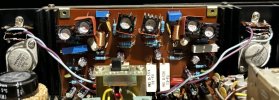
So as promised here is the amp board. Two pots added for adjusting bias, and two pots added in each side (one blue and one white, 500 ohm each) to adjust offset.

All low power transistors and, resistors, and caps replaced on this board.
Final values:
DC Offset = 4mv
Bias (takes 5 minutes to warm up to final bias value) = 14 mv (starts at 8 when cold).


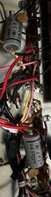
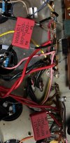
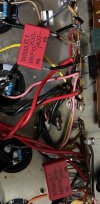
Also went back and replaced the two oil caps for new film caps. No idea what they do but the old ones are gone.
Old:
IMG_9975.jpeg


New:
IMG_9976.jpeg


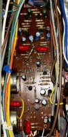
Also never gave a good pic of the tone board all finished and tucked away. All caps and transistors replaced in tone board as well. Alas it was too tight to replace all resistors but most were at exact original values.
IMG_9977.jpeg

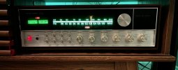
And finally I changed all lights out for LEDs. Here are the final beauty pics.
IMG_9971.jpeg

Fully Installed in wooden case inside wood cabinet.
IMG_9979.jpeg


Prologue: One day I’ll get around to changing out the tuner caps and resistors but I don’t really use it tbh so for now I’ll leave it be. I have all the parts but I’m tired and want to move on for now.
If anyone has any other tips for parts that might need replacing to future proof this beast please let me know :)
 

Attachments

  • IMG_9976.jpeg
    IMG_9976.jpeg
    91.5 KB · Views: 24
Those oil filled caps are usually there to keep the power switch from arcing internally and burning up the contacts when you turn it on and off. I don't have a schematic for the 930 but depending on exactly how the caps are wired, you'll probably want to replace them with either an x or y rated 250VAC safety cap.
 
Diodes came in today and installed them on both sides, screwing this back into the heatsinks.
View attachment 3197400

Once installed I then went to bias again, where both sides now hung around 9mv max. Letting the receiver warm up for 15-20 minutes while I made pizza they then settled out with a max of 15mv with the speaker button pressed inwards (allowing signal path to 8ohm resistors on output), and around 13 mv without the speaker button pressed in. Anyone care to explain why my max is around what is wanted for bias, and I can't actually get it to go over with the pot? It just goes up to 15, and if I keep turning it goes right back down.

Anyways! Checked offset and it is still down from 120 to 40 on each channel with new transistors installed.

Hooked it up and damn, even with the offset still a little high this thing is inky blank in the background. Not that it was loud before but it's just dead silent now. I will say the bass is everrrrrrr so slightly neutered compared to what it was but perhaps this will take time to come back (is burn in real?) or it could just be the Citation 11 I have it plugged into now being the culprit of this slightly change.

Next up:
Install proper resistors to adjust offset to 0 as best I can.
Remove output transistors and add new thermal paste.
Install LED lights that are coming in.
Change resistors on amp board if I'm feeling ambitious.
Recap FM section though I really won't and don't use it.

Are you adjusting bias while on dimm bulb tester? That will give you a false adjusting, as it will get to high bias as you plug it into the wall. If you did adjust with the wall-outlet, have you set the correct voltage for the transformer? 220v/240v?
 
Okay, So update. It really was quite the challenge to get to the tone board but we did it and only had to clip a few wires to get there. I've found that clipping the wires and resoldering them is easier on this unit. The techs that worked these wrapped the wires tightly around the pins and it's impossible to get the solder free. Anyways, the kit I bought is missing quite a few capacitors (Not impressed for 135 dollars - sigh-). So I had a question on a few parts.

For the 2 film caps on the tone board they are blue and read 104k, what are a good replacement for these while I'm in there:
View attachment 3185414

Now I'm learning on this next step so bear with me. I think I'd like to replace all the smaller transistors on this toneboard given that I have it out (again it took almost an hour to safely remove it) plus I'm looking to learn about transistor replacement. To keep original sound there are three smaller transistors on this unit. Any suggestions for good, modern, perhaps better performing replacements?
1) 2SA564
2) 2SC644
3) 2SC828

I was thinking of using this website which finds direct replacements: Alltransistors.com

When choosing replacements is it best to find exact matching or improve and exceed while you're at it (like the voltages on cap replacement) .

For example, it appears these 2222A transistors I have spares of exceed the values or the 2SC644, does that mean I can use it?

Thanks for any and all help!
Must have gotten the same inadequate kit I got from hifiaudio. I feel your pain. Quick question. I’m redoing my HK 930 and was wondering how difficult it was to remove the tone board and amplifier board. Love the post here. -G
 
Must have gotten the same inadequate kit I got from hifiaudio. I feel your pain. Quick question. I’m redoing my HK 930 and was wondering how difficult it was to remove the tone board and amplifier board. Love the post here. -G
Was pretty pissed. Then the dude blocked me from the PDF when I messaged him saying the kit was incomplete. NOT a good company.

Anyways, yeah it’s a bear, you have to take off the front plate and remove the dial cord slightly. Then disconnect or snip any cables connected to the tonearm board and gently wiggly it out of the mess of wires. Putting it back in to solder was just as much fun ‍
 
i have used speaker gasket foam before but then i started thinking about 20 years down the road when the foam dry rots and the cap falls out:eek:

now i buy the proper size or buy new clamps.

i bought some fat kemets for the 930 i did.
Had the same issue. Recap kit came with 35mm caps and the originals are 40mm diameter. Ended up deciding to buy some 35 mm clamps. But I found out I would have to drill another hole into the chassis to mount those clamps. Decided to just bite the bullet and bought some 40mm caps on DigiKey that fit in the original mounts. Upped the voltage and the capacitance also on all four of them. Glad I did.
 
Oh man, sorry to revive a somewhat older thread, but I think I found my people! I purchased a kit from hifiaudio for my MA5100 and I got PS caps that were totally different dimensions than what was called for as well as other caps of wrong value. They were way way taller, so he got really angry with me when I wanted to return and blocked me. He wanted me to cut my walnut cabinet with a saw rather than accept a return. I figured I would just pay a premium and get what I needed (this obviously did not happen). I did buy a volume pot from him which was great.

I did just buy a bunch of new signal path film caps from mouser (due for delivery today) if anyone wants lead-spacing and cap/V data for them.


For the HK transistors, I think the replacements are as follows (this is from one post, but the folks seem to know their silicon). My next amp on the bench is an HK 330B.
2SA564: KSA1015YTA
2SC644: KSC1845FTA
2SC828: KSC945CYTA or for a low noise option the KSC1845FTA (provided current is low enough)
 
Oh man, sorry to revive a somewhat older thread, but I think I found my people! I purchased a kit from hifiaudio for my MA5100 and I got PS caps that were totally different dimensions than what was called for as well as other caps of wrong value. They were way way taller, so he got really angry with me when I wanted to return and blocked me. He wanted me to cut my walnut cabinet with a saw rather than accept a return. I figured I would just pay a premium and get what I needed (this obviously did not happen). I did buy a volume pot from him which was great.

I did just buy a bunch of new signal path film caps from mouser (due for delivery today) if anyone wants lead-spacing and cap/V data for them.


For the HK transistors, I think the replacements are as follows (this is from one post, but the folks seem to know their silicon). My next amp on the bench is an HK 330B.
2SA564: KSA1015YTA
2SC644: KSC1845FTA
2SC828: KSC945CYTA or for a low noise option the KSC1845FTA (provided current is low enough)
I avoid Mr Hi-FI audio at all cost Search on this site for him. Not a lot of good remarks. Avoid avoid avoid!
 
@mcaddie7 I hear that! I'm liking the sound of it as well. You've got some great photos here and I shall follow them as I work on this unit.
As I'm working on this one, the schematic does not tell me what voltages the supply is outputting for B5 & B3. Do you recall what you had from those? I've got this one working, but before I recap, I'm trying to make sure it's working correctly. I've got some thermal photo that I am not sure if the operating temp of some of the components is correct. Thanks
 
I'm very curious how you got the tone board out to service. Did you de-string the tuner? I can't see a way to get the tone board out without destringing the tuner and releasing the front sub chassis to get room to pull the board.
 
BUT, the wires soldered to them need to be removed and they are double wrapped around and through each post and then soldered. It's a pain to remove and I almost wish someone took less pride in their work
If the wires are soldered to only one end of the pins, quite often the pins themselves can be unsoldered from the board leaving the wrapped wire intact on them. This way, after reassembly, the pins will retain the neat factory wrapping making it hard to tell the boards have been worked on.
 
I'm very curious how you got the tone board out to service. Did you de-string the tuner? I can't see a way to get the tone board out without destringing the tuner and releasing the front sub chassis to get room to pull the board.
Exactly this it is such a pain. I restrung the tuner, and clipped most all wires to the tone board and it was STILL hard to get out.
 
Back
Top Bottom