Yep. Good catch!That must be a typo as I'm sure you meant the KSC1845F.


Yep. Good catch!That must be a typo as I'm sure you meant the KSC1845F.

Thank you for this wonderful explanation. I plan on reading your guide today on my lunch break. Also apologies for the multi threads, I get a little over zealous at times.For transistors in the audio signal path, a generic 2222A would not be the best choice.
It is OK to look for a replacement transistor that "meets of exceeds all specs", but is also not the best way to go. For many reasons. To learn more, here is a start: Transistor Replacement Guide.
Better would be to search AK here to see if anyone has done similar (asked about this and gotten replies, potentially a discussion). Like https://www.audiokarma.org/forums/index.php?threads/hk-930-tech-advice.757415/
The best thing to do, however, is:
- For a given transistor in a specific circuit, like "TR101 on the tone board in a HK 930"
- Post here or in a new thread
- Tell us where the transistor is going to be used (i.e. "TR101 on the tone board in a HK 930")
- Post an image of the schematic (so those of us who don't have the service manual you're using can easily follow along and help)
- Tell us which transistor you want to replace
- Ask for help with that specific transistor being used in that particular spot of a specific circuit
That tells us the application of the transistor. That knowledge helps to guide us to which parameters are important, which are not, and, sometimes, which of several replacements is best for that application.
I don't see any 2sc564 on the tone board; only 2sc644 and 2sc828:
View attachment 3185971
All of those are in the audio signal path, so you'll want to look for low noise small signal transistor replacement. Getting the specs of the original devices from alltransistors.com is a great first step.
2SC644
NPN
Power Dissipation (Pc): 0.15 W
Collector-Base Voltage |Vcb|: 25 V
Collector-Emitter Voltage |Vce|: 25 V
Emitter-Base Voltage |Veb|: 5 V
Collector Current |Ic max|: 0.05 A
Transition Frequency (ft): 75 MHz
Collector Capacitance (Cc): 10 pF
Forward Current Transfer Ratio (hFE), MIN: 350
Noise Figure, dB: not stated
Package: TO-92
Pinout: ECB
For low noise, since the above 2sc644 is low current 50mA and low voltage 25V, I'd start with looking at the KSC1845F.
KSC1845F
NPN
Collector Power Dissipation (Pc): 0.5 W (better than 2sc644)
Collector-Base Voltage |Vcb|: 120 V (better than 2sc644)
Collector-Emitter Voltage |Vce|: 120 V (better than 2sc644)
Emitter-Base Voltage |Veb|: 5 V (same as 2sc644)
Collector Current |Ic max|: 0.05 A (same as 2sc644)
Transition Frequency (ft): 50 MHz (lower than the 2sc644, but we're doing audio that only goes to 20KHz, so this is fine)
Collector Capacitance (Cc): 1.6 pF (better than 2sc644)
Forward Current Transfer Ratio (hFE), MIN: 300 (not quite as good as expected from 2sc644, but plenty fine)
Noise Figure, dB: not stated but amongst the best
Package: TO-92 (same as 2sc644)
Pinout: ECB (same as 2sc644)
All its (important to us and our application in this circuit) specs meet or exceed, it does very well as a small (audio) signal amplifier (which is what the application of the 2sc644s on the HK 930 tone board are doing), and it is ECB pinout.
2SC828
NPN
Power Dissipation (Pc): 0.25 W
Collector-Base Voltage |Vcb|: 30 V
Collector-Emitter Voltage |Vce|: 30 V
Emitter-Base Voltage |Veb|: 5 V
Collector Current |Ic max|: 0.05 A
Transition Frequency (ft): 110 MHz
Forward Current Transfer Ratio (hFE), MIN: 65
Noise Figure, dB: not stated
Package: TO-92
Pinout: ECB
Same thing here for the 2sc828: low current, low voltage, best to have low noise... so, again, the KSC1845F would be amongst the best choices.
All this said, it would also be helpful to read the first page of Noisy transistors to replace on sight as it may help you in your quest for what to replace and what to replace those with.
| Matching Pair: | Replacement |
| 2SA564A (x2) x2 - PNP | KSA992FBTA -PNP Link: https://www.digikey.com/en/products/detail/onsemi/KSA992FBTA/3163196 |
| Single | |
| 2SC828 x2 | KSC1845FTA - NPN |
| 2SC828 (x2) - NPN | KSC1845FTA - NPN |
| 2SC644 (x6) - NPN | Link: https://www.digikey.com/en/products/detail/onsemi/KSC1845FTA/1047631 |

I'd suggest buying plenty of these as the ones you use in this position on the board must be matched. Twenty, maybe even thirty should be enough to get two closely matched pair if you are going to do both channels.
Matching Pair: Replacement 2SA564A (x2) x2 - PNP KSA992FBTA -PNP

The guy who owns HiFi audio is great, I’d def check out his other stuff.
Learned this the hard way. Long story short I found for the second time he forgot even more caps and gave some incorrect ones. I asked if he could send these and didn't receive any response. Ebay wouldn't give any money back, so when I asked for a return from him I got reported. I then left a review of his service (was completely kind but honest) he flagged my review as "Derogatory" and it wasn't posted. Had to go through my credit card company to get a refund. Would absolutely nor recommend, guy is a con artist.No, he's not so great.
See here: https://audiokarma.org/forums/index.php?threads/can-anyone-tell-me-about-hifiaudio.1032226/

While I agree with you on buying in bulk, it's not really practical for some. If that's the case, purchase them on taped reels, usually indicated by TA at the end of the part number. You're much more likely to get them all either matching or very close in hFe because they are likely all from the same production run. Sort of a way to hedge one's bets. Also a good plan if one doesn't have a tester that can measure hFe.I'd suggest buying plenty of these as the ones you use in this position on the board must be matched. Twenty, maybe even thirty should be enough to get two closely matched pair if you are going to do both channels.
Well yes, but then again no.purchase them on taped reels, usually indicated by TA at the end of the part number. You're much more likely to get them all either matching or very close in hFe because they are likely all from the same production run.
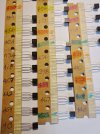
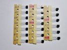
Exactly. I'll try to dial in the next set a bit better for a burned up 630 sitting on the bench right now as I might want to keep it for a while.Im more worried about vbe than hfe for diff pairs but i still try to get both as perfect as i can.
BumpUpdate:
So tone board was completely recapped and all transistors replaced with the ones mentioned above. Checked resistors and they were all very close barring three but the amp sounded amazing from a quick turn on. Put tone board back up in and buttoned up a cleaned and polished faceplate
Before changing transistors on Amp board I wanted to bias the amp. I replaced both pots with multi turn pots.
With source selected set to Aux, and speaker 1 on and my resistors in the back, I biased to 15mv. However, the left side would only go up to 6mv, and if I increased or decreased the pot the bias would then go down.
Any tips? Thinking one of the transistors is going bad? The amp physically sounds fine but I’m guessing it could sound better if I found the issue?

Hi! I'll try this out tonight when I go to dig in and replace the matched transistors. I do have a question though, why does the schematic show D621 and D622 being in parallel but when you look at the actual board / board schematic there is just one diode present on the Amplifier board? Also, when I get the replacement, do I put two of them in parallel to replace this or series? Any help is appreciated, thanks!hello,
i had this untunable bias problem on a HK 730, stabistor was failing though diode tested ok.
try exchanging KB265 stabistor diodes from faulty left side with the ok right side ones...
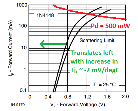
if it solve the problem you can replace each with pair assembled 2x 1N4148 in series
though direct replacement with 1N4148's in series is faster option...
View attachment 3195773
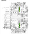

Found the ones From the schematic actually, they are off to the side above the output transistors. Would love to know why but guessing it has to do with heat.imho if there is no problem with them (faulty or known to fail with collaterals damages) let the genuine matched transistors...
you know the words "if it's not broken don't try to fix it" .... is even more valuable on these vintage materials.
one KB265 can be replaced by 2 x 1N4148 in serie so if there is only one KB265 great as it's simpler
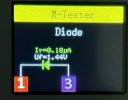
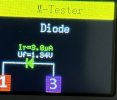
after desoldering test your KB265 to have Vf , should be arround 1,3V
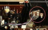
Thanks for the DC Offset post.yes they have to follow the heat of transistor to stabilise bias.
you can ad a 500ohms trim pot for DC Offset adjustement at R608 and R628 instead of 330ohms resistor
HK-930 Dc Offset Voltage problem
After reading the thread by EchoWars I tested DC offset, unfortunately all was not good, Left 29mV Right 124mV. After some great advice and info from EchoWars & Ecluser I have started a new thread as it is more specific to the 930. It appears there is no adjustment for offset voltage, so the...audiokarma.org