• The move to the new server is done. There are some software and database maintenance updates in process. This has us passing the hat around to help out. We appreciate any donations. Seriously, even a dollar helps. The payment page may be found here - https://www.audiokarma.org/support.html

Harman Kardon HK 330B recap, restore and upgrade BOM part list (kinda)

Doug, how have the LED fuse bulbs held up? I've got two pioneers that use them in the queue and I'd love to replace the fuse style lamps with something that'll put off less heat and last basically indefinitely. Got a specific seller you like to get them from?

I use warm white from Parts-Express. They sell them in packs of five (?) and id love to buy them in larger quantities.

The Parts-Express ones have worked very well for me and they are _slightly_ different from the many "generic" ones on eBay. The white board between the two end caps is cut nicely at the same diameter as the metal end caps. The generic ones on eBay all seem to have white boards that are 0.25mm wider than the metal end caps. This board width isnt the difference, but rather an indicator of different manufacturer.

I actually forget now what the performance difference was. Hah, typical for me. All I can say then is I like the ones from Parts-Express and those are the ones I keep buying. They work well for me and Ive never had anyone complain or report a problem.

And buying from Parts-Express gives you an opportunity to buy more of their old stock of Deoxit D5... in the old can style!

Let me know what your experience is with whatever you chose.
 
FM MPX board

As I mentioned before I've got no silkscreen on my boards and I can't find a proper picture of the MPX so I'm flying blind.


Yep, I hear ya. I should have asked you this before: will you snap a photo of the MPX board you have and send it to me? That way I can find you the right picture from my collection and give you credible guidance.

There are six 1µf 50V electrolytics on the board.

I used six 647-UKL1H010KDDANA caps, is good?

Those look perfect. Sometimes I find it hard to catch the 1uF 50V KL caps in stock. For those times, I just buy the 100V versions.

You could also put 1uF 50V or higher film caps in those spots.

Four 1335 transistors should be replaced as well I imagine?

I would not recommend replacing the transistors on the tuner nor the MPX boards. The differences in operating curves of the replacement devices could throw your tuning off (and require an alignment which requires more gear, kinda pricey, and lots of practice and patience).

You may get away with it in just the MPX board, but no reason to do that unless you find problems with reception or with stereo separation.
 
Just like yours as far as I can tell.
 

Attachments

  • IMG_20190225_140602~2.jpg
    IMG_20190225_140602~2.jpg
    97.3 KB · Views: 66
Just like yours as far as I can tell.

You have the multi-voltage euro-ready version since you have selctable FM pre-emphasis switch. cool!

There is one 220 uF cap and all the other electrolytic caps can be 1 uF. Here are the locations and polarities:

TUNER-FM-MPX-STRIPPED-IMG_6943.png

If the low res AK version is unreadable, send me a PM with your email address and I'll send you the original photo.
 
Figured it out, got into a rhythm forgot to verify. Missed the .47µf (assumed another 1µf). I'll fix that.

All done but the big kahuna, I think I'll solder a terminal onto the little "snap-in" nubbin so I have a better chance of fitting all the wires.

Again, thanks for the work. I've been collecting busted stuff and having this resource (AK) to help me fix them is priceless.
 
Hurray!!!
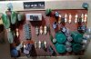
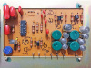
After what seem like 40hrs making my BOM, unsoldering than soldering I got my beautiful HK 330B RESTORED. I only did the PSU, the control board, the RIAA board and the amplifier board changing almost everything on your list. I kept the non-problematic transistors. I never listen to radio so I skiped the rest. In Rainbows from Radiohead is now playing in my Martin Logan Motion 15 ind it sound super sweet. I would not say I can tell the difference from before but at least I know it’s not going to give up anytime soon. I’m in love with the look of this receiver. Those rocking switch and this tuning scale, no other receiver can beat that.

Thanks for your generosity Dlucy.

One small question. I’m intimidated by changing the 4 adjustable resistors on the amplifier board. Could you explain those steps to us please?

Thanks again.
 

Attachments

  • 516324EB-F95C-493C-8061-A6F219AC485E.jpeg
    516324EB-F95C-493C-8061-A6F219AC485E.jpeg
    88.2 KB · Views: 87
  • C7F5AB58-482D-488F-BE81-BD39A5EEF4F9.jpeg
    C7F5AB58-482D-488F-BE81-BD39A5EEF4F9.jpeg
    120.2 KB · Views: 84
Hurray!!! After what seem like 40hrs making my BOM, unsoldering than soldering I got my beautiful HK 330B RESTORED.

Excellent! Feels good, right? It is really hard to have a span of days or weeks between starting and finishing to do a mental A/B test. I can send you an untouched 330 if actually hearing the diff is worth shipping to you and then ack to me. ;)

Gimme a day or two and I'll assemble some photos and description on the trimpots. Replacing those won't make any audible difference, BUT Ive had the trimpots from more than two units literally fall apart as I tried to adjust them. That is a BIG risk to the unit if power is on. But replacing the trimpots are definitely optional.

Again, great work! Now you need to pick a second unit of some kind to continue getting hooked on restoring. ;)
 
Wow thanks Dlucy that’s an awesome offer and I’m very tempted but I will pass. I actually did an AB test vs an HK AVR220 that I got for 60$ just so I had something to listen to while restoring my beloved 330B. I just finished redoing the same AB using my favourite AB song(Why You Wanna Trip On Me by MJ)and I can feel the improvement very clearly. Before the restoration the 330B was slightly better and now it’s very evident that the 330B is winning the AB. I would say the Lows and the Mids improved a lot. The highs are as good as they where if not better. I moved on and AB with my Cyrus 1 that I recapped last year and the Cyrus is ahead for its clarity but the 330B is supposed to be warm and it is and I would say I like them equally.
 
One small question. I’m intimidated by changing the 4 adjustable resistors on the amplifier board. Could you explain those steps to us please?

So, you have to replace a trimpot. Here is an incomplete guide:

First, does the original trimpot have two legs? Or three? You should be able to tell from the board where it is soldered in or from the schematic. Two-legged trimpots are just variable resistors. Three-legged trimpots are potentiometers. (I may have the terminology wrong here; I'm just a hobbyist)

IMG_6839.JPG wiper and legs.png

If your original trimpot has just two legs, then you'll need to buy a three-legged trimpot and intentionally short the wiper (middle leg) to one of the two outside legs. This makes it a variable resistor instead of a potentiometer. If you don't short the wiper to one leg, then you have a fixed value resistor. That is not what you want.


Example: https://www.audiokarma.org/forums/i...arman-kardon-330c.781237/page-6#post-11943536

Example: https://www.audiokarma.org/forums/i...ng-a-harman-kardon-330c.781237/#post-10810244

So, regardless of the original, you need to order a three-legged trimpot. Be very careful when ordering:

Many online parts sites (Mouser, I'm looking at you) show little photos of trimpots, but the photo is not necessarily the same as the part you are ordering. For example. you may find there is a Bournes that has the right value, the picture looks like what you want, order it and learn that it has the pins with the wrong layout or spread. This can be learned.

Example of some layouts https://www.audiokarma.org/forums/i...oration-and-recap.815087/page-3#post-11944007

Examples:
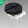
3352 image.png 3386 image.png

So, for our example, the Bournes 3386 trimpot is the type/shape/turns/whatever that we want, we've picked the right resistance value, and now Mouser shows 3-4 of the same-looking trimpot but each has a different letter at the end of the part number.

That letter is what you need to look up in the datasheet. Download the datasheet by clicking on the link at the parts site for that part, read the variant pinout styles carefully, and then choose the model and part number/letter that will fit. Or fit closest.

And you'll want to use the diagrams in the datasheet to determine which orientation of trimpot do you want. Often you'll want the same as the original since that orientation should allow easy adjustment once the parts have all been soldered in.

"top" means you adjust from the top. "side" means you adjust from the side. You can choose a more convenient orientation, but check how much space the trimpot will take up on the board and how you'll get a screwdriver to the trimpot to adjust once the unit is back in operation.

The datasheet will also help you determine if you have enough space (on the trimpot) to roughly meet the holes in yur board.

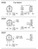
3352 side.png 3352.png
 
Thanks Dlucy,
That is helping, I did not know what to think of the middle leg. Now I know.
As for the setting of those resistors. If you don't have an oscilloscope, could you check the resistance if the old one with a multimeter and set the new one to the same value? Or is that a NO NO?
 
Thanks Dlucy,
That is helping, I did not know what to think of the middle leg. Now I know.
As for the setting of those resistors. If you don't have an oscilloscope, could you check the resistance if the old one with a multimeter and set the new one to the same value? Or is that a NO NO?

Yes, that's right: you can measure resistance with a multimeter (now called DMM) or a "cheap component tester". You do not need an oscilloscope.

Good article on "cheap component tester": http://audiokarma.org/forums/index.php?threads/cheap-component-tester.749729/
 
Well, job completed, the four trimpots are replaced, idle voltage needed to be adjusted to 8mV on each channel, they were almost at 0mV and DC balance adjustment was fine.
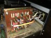
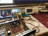
Clipping tested at 40Vpp on 7.5 ohms load giving 26.7 WPC. She is now part of my living room and she fits perfectly with the Technics SL-Q2 and the JBL L50. I would recommend this adventure to everyone. One little thing, maybe replacing the 3K trimpots with newer 3K trimpots instead of 5K would make the idle adjustment easier.AC07E6A8-B04D-4052-8DBE-85AF6BE0C580.jpegE62EB00F-12C1-48FE-80AC-E276E3F729D6.jpegFF4C98B9-03B4-4C58-9D15-0FA8EF988D8B.jpeg
 
Well, job completed, the four trimpots are replaced, idle voltage needed to be adjusted to 8mV on each channel, they were almost at 0mV and DC balance adjustment was fine.
Clipping tested at 40Vpp on 7.5 ohms load giving 26.7 WPC. She is now part of my living room and she fits perfectly with the Technics SL-Q2 and the JBL L50. I would recommend this adventure to everyone. One little thing, maybe replacing the 3K trimpots with newer 3K trimpots instead of 5K would make the idle adjustment easier.View attachment 1492131View attachment 1492132View attachment 1492133

Well done!
 
After reading a lot of restoring vintage audio gear threads here on AK, I've learned there are numerous, popular transistors that were used in these units which often degraede in performance over several decades. These old transistors now introduce clicks or pops or hum or static into the signal they are handling. The result is annoying artifacts in your sound or just less-than-expected fidelity.

Many people on AK have mentioned this, lots of people have contributed advice like "you should replace that noisy old 2SC458 with a modern KSC1845F" in various threads, and there is a recent thread that collects this information in one place for ready reference. I got jealous of all the well-made Pioneer SX series receiver recap lists where these were mentioned the most and created a new thread so people working on non-Pioneer gear might find some help as they recap or repair or restore other gear.

http://www.audiokarma.org/forums/in...ilure-prone-whatever-and-replacements.731653/

If you find other advice on replacing old transistors like this due to age-related failure, please post it in that thread.

Noisy transistors in Audio circuits will generally sound very hissy but if taken out and tested will generally test good in most transistor checkers and still be bad. In power supply's particularly those for receivers, noisy transistors will generally still test good in most transistor checkers but produce hum. You will replace all the caps in the power supply and still have hum making its way into your audio circuits.
 
Leaky transistors in Audio circuits will generally sound very hissy but if taken out and tested will generally test good in most transistor checkers and still be bad. In power supply's particularly those for receivers, noisy transistors will generally still test good in most transistor checkers but produce hum. You will replace all the caps in the power supply and still have hum making its way into your audio circuits.

I just recently purchased a Harman Kardon 330B off of ebay for 160.00 shipping included. When I received it about a week ago and took it out of the box it looked as if the person who originally purchased it had never used it and had it in storage since 1973. Pristine in and out. The only thing wrong was that the phono circuit was noisy in one channel. Still worked but noisy. I therefore opened the unit up and replaced all 4 transistors on the phono preamp board with the 1845 (probably just one out of the four was leaking but you might as well get them all, took 15min) . Noise is now gone. Normally I would replace all the low power transistors and capacitors but aside from the transistors in the phono board nothing else is wrong. I mean nothing else!!!! AM and FM tuner components are still aligned etc!! Lights are all good, no scratches etc etc. Plastic tuning dial and aluminum front are all pristine. I will include pictures shortly. The transistors in the phono section probably just degraded from age rather than use.
 
Last edited:
I just recently purchased a Harman Kardon 330-b off of ebay for 160.00 shipping included. When I received it about a week ago and took it out of the box it looked as if the person who originally purchased it had never used it and had it in storage since 1973. Pristine in and out. The only thing wrong was that the phono circuit was noisy in one channel. Still worked but noisy. I therefore opened the unit up and replaced all 4 transistors on the phono preamp board with the 1845 (probably just one out of the four was leaking but you might as well get them all took 15min) . Noise is now gone. Normally I would replace all the low power transistors and capacitors but aside from the transistors in the phono board nothing else is wrong. I mean nothing else!!!! AM and FM tuner components are still aligned etc!! Lights are all good, no scratches etc etc. Plastic tuning dial and aluminum front are all pristine. I will include pictures shortly. The transistors in the phono section probably just degraded from age rather than use.

That is an excellent find!

A few points to consider:

1. Small signal transistors that “go noisy” as they age have to do with age, not use. So, the 2SC458 transistors that everyone complains about have a type of noise that comes from the legs corroding as they enter the plastic case and that allows the internal transistor to oxidize in some way.

There are several age-related kinds of small signal noise. There is a link to the online research papers documenting these kinds of noise in the “top ten transistors to replace” thread: https://www.audiokarma.org/forums/i...ilure-prone-whatever-and-replacements.731653/

2. In the 330A and 330B, the small signal transistors that “go noisy” are found in the EQ / PHONO stage board *AND* the preamp / control board. You will reduce noise for the PHONO circuit by replacing the transistors on that board, but EVERYTHING is affected by the “go noisy” transistors on the preamp board.

3. If you still have any original electrolytic caps, then you are not hearing the full glory of this receiver. Electrolytic caps don’t just go bad suddenly. They degrade in performance from day one, so they may still be functioning but not properly.

This is especially true for the two output capacitors (big ones on each main amp board). To a great degree, these are the key to the 330 sound.

Just for your information. ;)
 
That is an excellent find!

A few points to consider:

1. Small signal transistors that “go noisy” as they age have to do with age, not use. So, the 2SC458 transistors that everyone complains about have a type of noise that comes from the legs corroding as they enter the plastic case and that allows the internal transistor to oxidize in some way.

There are several age-related kinds of small signal noise. There is a link to the online research papers documenting these kinds of noise in the “top ten transistors to replace” thread: https://www.audiokarma.org/forums/i...ilure-prone-whatever-and-replacements.731653/

2. In the 330A and 330B, the small signal transistors that “go noisy” are found in the EQ / PHONO stage board *AND* the preamp / control board. You will reduce noise for the PHONO circuit by replacing the transistors on that board, but EVERYTHING is affected by the “go noisy” transistors on the preamp board.

3. If you still have any original electrolytic caps, then you are not hearing the full glory of this receiver. Electrolytic caps don’t just go bad suddenly. They degrade in performance from day one, so they may still be functioning but not properly.

This is especially true for the two output capacitors (big ones on each main amp board). To a great degree, these are the key to the 330 sound.

Just for your information. ;)
I'll probably do a cap and low power transistor replace eventually but this is such a pristine unit that it Pains Me Greatly:( to even do what I did with the Phono section.
 
I'll probably do a cap and low power transistor replace eventually but this is such a pristine unit that it Pains Me Greatly:( to even do what I did with the Phono section.

I also have an HK 930 receiver which was their top of the line stereo receiver I think between 71-74 or there abouts. This one was mint as well when I received it. Still has the plastic wrap attached to the front of the aluminum.(I left it alone) I replaced all the transistors on the pre amp tone amp board with the 1845s. I replaced all the electrolytic caps in the entire receiver. But used primarily ELNA SILMAC II's for the tone amp/preamp board and the amplifier board. For the phono amp\equalizer I replaced the caps with ELNA SILMAC II's but replaced the stock transistors with NTE 199's Rather than the 1845s! I like the bite that these transistors produce in the phono circuit. I replaced the output power transistors with 250 watt units rather than the stock 125 watt transistors and readjusted the idle voltage with no issues. This receiver has the more modern wood case. I think it dates from the end of the 930 run so probably closer to 74 or even early 75. I'll send a picture of this one as well.
 
Last edited:
Back
Top Bottom