• The move to the new server is done. There are some software and database maintenance updates in process. This has us passing the hat around to help out. We appreciate any donations. Seriously, even a dollar helps. The payment page may be found here - https://www.audiokarma.org/support.html

Harman Kardon HK-590i high voltage output to right speaker terminal

CouchPotato

New Member
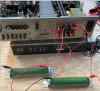
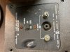
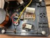
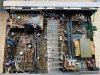
Hi Everyone, I bought the receiver over the weekend and wanted to fire it up and hooked it to my Nova 6 speakers. I noticed a high pitched whine from the right channel and caught a whiff of that bad burning electronic smell. Checking into it I saw the crossover plastic cover had melted and when I took the speakers apart there was a fried resistor in the crossover. I looked at some other post on the site and saw mention of connecting to a pair of dummy loads and turning it on with all the with all options off and volume down. The right channel had a voltage reading of 29.1 volts and the left channel was .464 volts which explains the cooked crossover. I've downloaded the service manual and have spent time identifying the components and boards but need help with how to continue the troubleshooting and repair of this receiver. Great lesson on the need for a dim bulb tester. I've posted some photos of what I've come across so far. The red circle on the cover was where there was smoke residue after the "incident" although nothing was visibly fried on that side.
Any help would be appreciated.
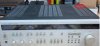
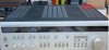
HK-590i front with cover.JPG
HK-590i cover off.JPGDummy load hooked up to speaker terminals.JPGRight channel Speaker terminal voltage.JPGLeft channel Speaker terminal voltage.jpgNova 6 Crossover outside burnt.jpgNova 6 fried Resistor.jpg
 

Attachments

  • HK-590i front with cover.JPG
    HK-590i front with cover.JPG
    26.6 KB · Views: 4
Register to hide this ad
The right channel had a voltage reading of 29.1 volts and the left channel was .464 volts
Possible shorted output transistor for the right channel.. Post a photo of the backside of that big aluminum heatsink running through the center of that receiver.

Need to check Q422 and Q424 for shorts.
 
Last edited:
just a note. you dont need dummy loads to look at the output offsets .it could in fact make things worse . and yes i agree its looking like suspect outputs and maybe drivers .
 
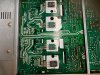
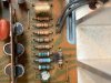
Thank you @avionic and @petehall347 for the reply. Here is a photo of the output transistors on the heat sink. I de-soldered C422 and have been trying to make sense of the multi-meter readings. I circled a group of 5 transistors with what looks like a heat sink clamped to it on the other side of the board. I also see a burnt resistor near the transistor grouping. The is an identical group of 5 transistors are on the other side of the board, I'm guessing for the other channel that is working OK. The solder connections look a little rough so I think at one time it was worked on. I removed Q422 so I could test it. My question at this point, did I need to remove a transistor to test it right or is there a way to test these in circuit?HK-590i Output Transistor on heatsink.jpg HK-590i burnt resistor.jpg
 
R460 is the burnt resistor it is a 82Ω 1/4 watt , flame proof ...

Need to check these 6 transistors..

Q418
Q420
Q422
Q424
Q426
Q428

Q422 and Q424 are the two large transistors fastened to the large aluminum heatsink ( one black and one green ).
 
Last edited:
Avionic nice tutorial on transistor testing, thank you. I pulled the transistors and tested them. I also took out and tested Q416 since it was part of the assembly with the heat-sink holding the others. The results are below, I used the diode setting on my meter for the test. Thank you for your help with this.
Q416
Q418
Q420
Q422
Q424
Q426
Q428
hk-590I TRANSISTOR TEST RESULTS.JPG
 
Looks like you need to go shopping for some transistors Q416,420,Q422 and Q426 are shorted..
Q424 needs to be replaced as well due to it being the complement to Q422.

Q416 -- 2SC945 -- 2SC945A
Q420 -- 2SA817 -- 2SA817A
Q422 -- 2SC3182 -- 2SC4468
Q424 -- 2SA1265 -- 2SA1695
Q426 -- 2SA965 -- 2SA965
 
Last edited:
Thanks Avionic, I took a look at Q418 datasheet and I had the right one. I've attached it. On Q418 neg base with pos collector is .027 with an alarm so we can add that one to the list. I'm not sure what I was seeing last night, went a bit late... What can I look for upstream that could have caused these all to go on this channel while I'm waiting for the parts? I'll order the transistors now, I appreciate the new source. I didn't have any luck looking for Q422 & Q424 only found them on the auction site or direct from China


. Q418 Spec sheet.JPG
 
. What can I look for upstream that could have caused these all to go on this channel while I'm waiting for the parts?
Down stream--- Output transistors shorted out causing collateral damage through the NFB circuit.
 
2SC1627 not available at B+D.. sub 2SD667A
 
Last edited:
That's great, I was just looking for 2SC1627 when I found it wasn't available. The rest are ordered. I'll order a couple of the R420 resistors with the 2SD667A transistor. Is there a place where I could look up an equivalent part like 2SD667A, or is that gained from experience?
Thank you.
 
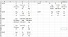
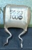
Hi, I had another question. While I was waiting for the parts to come in, I thought I would check easy to access capacitors and started with the EQ board PCB-4 There are some white "chiclet" shaped capacitors. When checking them I couldn't get a reading then realized they are really small values that my DMM wouldn't register. Is there a way to check these? Do they usually go bad? I did my best on Digikey and Mouser but no luck, nothing that small. I'm hoping these aren't temperature sensitive since I already removed one with desoldering braid.
EQ PCB.JPG C610 Eq capacitor.JPG EQ capacitor list.JPG
Thank you
 
@avionic, @petehall347 I finally got the receiver working after replacing all the transistor's and 10 Capacitors that had an ESR over 3. The right channel that was blown has a bit of a tinny tone to it compared to the left, both have about the same volume and sound good when played together. Where can I start troubleshooting this issue, or is there a break in period for new parts?
Thank you for all the help!
 
Back
Top Bottom