• The move to the new server is done. There are some software and database maintenance updates in process. This has us passing the hat around to help out. We appreciate any donations. Seriously, even a dollar helps. The payment page may be found here - https://www.audiokarma.org/support.html

Harman Kardon PM640, what is this burnt thing?

Hi,

Boy, what lack of sound engineering practice on this model. No heatsinking or meaningful circuit protection. A miracle it didn't flambe the amp and/or speaker system. I understand not wanting circuit protection in the way of your music but you need some safety circuitry in case of thermal overload or amplifier instability.
 
The problem is much more serious than a transistor replacement.

Whatever the transistor you will put there, the actual heat sink is too small for the power dissipated by the driver transistors. At standby, each driver must dissipate approximately 3/4 Watt. This is very close to the maximum power for them.

http://www.datasheetarchive.com/pdf-datasheets/Datasheets-39/DSA-767031.pdf

If you can't keep your fingers in contact with the heat sink more than a second, the transistor temperature is probably 70 degree C or more.

Fortunately for me, my PM640 is used only with headphone. I will take a closer look at this and propose a modification to improve reliability. This will certainly imply a new heat sink and higher power package.

Using a cheap Sears digital meter, I'm getting 145-150 degrees F on the heat sinks depending on how close I get to the actual transistors. Which I guess converts to about 63 - 66 degrees C. Switched to Celsius and got meter readings about 62 to 66 C up to 70 C again depending on how close to the transistors. I think it stabilizes under 70 C though hitting 67 or 68 occasionally as I move the probe around.
 
Using a cheap Sears digital meter, I'm getting 145-150 degrees F on the heat sinks depending on how close I get to the actual transistors. Which I guess converts to about 63 - 66 degrees C. Switched to Celsius and got meter readings about 62 to 66 C up to 70 C again depending on how close to the transistors. I think it stabilizes under 70 C though hitting 67 or 68 occasionally as I move the probe around.

is that after you cooled it down with your tweak??
 
is that after you cooled it down with your tweak??
Yes.

Temperatures were taken today after the tweak which I did the other day. Heat sinks attached to the drivers are still too hot to the touch. But I may just be a wimp if 70 C is ok.

What I had noticed cooled down were the long heat sinks that run the length of the amp.

I just read the temperature on the 3 long heat sink fins that run the length of the amp and they are much cooler at 43 to 44 degrees C which would be about 109-111 degrees F. Much cooler to the touch.
 
At standby, each power transistor dissipates 2.6W (only three times more than the drivers) but the large heat sink is much, much, more efficient than the driver's heat sink.

You have a better measure about the thermal problem here...

I figured 70 C because when you touch a surface at 65 C, you feel pain.
 
As an alternative, you may replace R439/440 for a larger resistor, say 220 or 330 Ohm.

This will cool down the drivers.
 
Would it have any adverse effects?

No severe adverse effects. But, yes, there is some adverse effects.

The Gain Bandwidth product will be lower, and the current gain will be lower. By how much? Approximately by 30 to 20% respectively.

Note that the amp will be more stable, less chance to oscillate.

With a 220 Ohm resistor, the current in the drivers will be 5.3mA, and power dissipation will be 185mW for each drivers. The driver's heat sink should stabilize at ~35C
 
Those look to be the Output drivers.
You can find the service manual at:
"http://manuals.harman.com/hk/Service Manual/pm640 sm.pdf"

Q417,Q418 2SC945 (K)or(P)

Q423,Q424 2SC667 A(C)

Q425,Q426 2SB647 A(C)

Hope that helps.

First thanks for the service manual! :thmbsp:

Checking the service manual it looks like

Q423,Q424 2SD667 A(C)

But that to me in no way diminishes my appreciation of your help. It's my responsibility to double check and review anything from the Internet for my use. :yes:

In fact, before this thread goes into oblivion, I want to THANK ecluser and the rest for a very educational thread. Another step in learning here.
 

Attachments

  • pm640Trans.jpg
    pm640Trans.jpg
    88.1 KB · Views: 49
No severe adverse effects. But, yes, there is some adverse effects.

The Gain Bandwidth product will be lower, and the current gain will be lower. By how much? Approximately by 30 to 20% respectively.

Note that the amp will be more stable, less chance to oscillate.

With a 220 Ohm resistor, the current in the drivers will be 5.3mA, and power dissipation will be 185mW for each drivers. The driver's heat sink should stabilize at ~35C

Besides the negative sonic effects and the cooling improvements, will there be any improvements to the sound?
 
Sir.Byrd,
I didn't say there would be negative sonic effects...

If you project the curve for the "Gain Bandwidth Product" vs "Collector Current", on the 2SD667A sheet, you will find a fT close to 40MHz at Ic=5.3mA

The (C) version of this transistor has a hFE between 100 and 200, take a mean value of 150

This means this transistor will have a current gain of 150 from DC to 260KHz (260 KHz = 40 MHz / 150), and the current gain will fall to one (0dB) at 40Mhz.

There will be no adverse effects up to 260KHz (enough for me!)

With the original collector current (21.5mA), the gain will hold up to 520KHz and fall to one at 80MHz. In fact it is not exactly this because at high temperature, the hFE is higher by a small amount and the cut-off frequency will be lower than 520KHz.

Don't forget that until now, I talked about the power dissipated by the drivers at standby only, with no audio signal. When there is a large audio signal at the output, the power output transistors will need some base current. This base current will ad to the standby DC current in each driver in alternance, the NPN driver will work harder on positive output signal and the PNP driver will work harder on the negative part of the output signal.

Add to this the fact that inside the amplifier, with the steel cover in place, the ambiant temperature is higher than 25C, maybe 50C. At 50C, the max power for this transitor is 700mW

Enough good reasons to try to cool down the drivers.

terra1,

Sorry that you missed my post #15 about the 2sD...

Since you have a nice thermometer and you like to play with it, would you try to swap the 56 Ohm (R439/440) for a 220 Ohm resistor (1/4 W) and report the result?
 
Since you have a nice thermometer and you like to play with it, would you try to swap the 56 Ohm (R439/440) for a 220 Ohm resistor (1/4 W) and report the result?

Sounds like a plan to me. Its kind of handy how we all have a PM640.
 
It's odd that H-K would underdesign the drivers like that, if in fact it is a design issue... I've got a PM650 with the same heatsinks on the drivers/predrivers, it also uses 2SC945's as pre-drivers. They run cool enough that there is no burnt thermal paste, no burnt PCB, etc. They use 2SA965/2SC2235 for drivers though which are rated higher. The heat sinking on the PM650 outputs is WAY WAY WAY more heavy-duty than the PM640. I also do not drive low impedance loads at high volume.

Those heat sinks on the drivers are a WHORE to get apart and back together again... you have to put paste on all the transistors and bend the clips back on, then adjust all 15 leads to go through the holes in the PCB. If you try to move the transistors to fit into the clips after they're soldered in place, you'll end up breaking a lead (don't ask how I know).

I wouldn't use an amp like this for driving a low-impedance load at high power, they're just not designed to do it and generate way too much heat for the heatsinking employed. People who try to drive two pairs of low efficiency speakers in parallel at high volume need to realize that consumer-grade gear is, in general, not cut out for it. Run them in series and give your poor amp a break.

2SC945 has got to be one of the most common transistors ever and are found in zillions of devices.
 
Last edited:
Boy looking at those pictures the PM640 and PM650 couldn't be more different. the PM650 is very well-built, there are no ribbon cables, the connections between boards are all wirewound, the heatsink on the outputs is much more substantial and the power supply is much beefier. The phono section is on its' own board which is as high and deep as the case, having both MM and MC inputs and variable capacitance adjustment.
 
Since you have a nice thermometer and you like to play with it, would you try to swap the 56 Ohm (R439/440) for a 220 Ohm resistor (1/4 W) and report the result?
I'm glad I got a model with a thermometer, does come in handy. It's a Craftsman 82334. Seems to do what I need for a beginner. Wanted a Fluke 117 but those are at least twice as much.

I replaced the 56 ohm resistors with 220 ohm 1/4 watt resistors.

Fry's did not have a complete set of transistors so I didn't mess with replacing those. But I think it's just as well to see how the resistors take and perform on their own.

After 20 minutes the temp around the transistor heat sinks was about 36-39 C. Checked the test points and they were down about 21.4 mV left, 23.6 mV right.

Readjusted to 33 mV and temp went up to about 38-40 C depending on how close I measured to the transistor.

A remarkable improvement. Very touchable.

By the way, while looking for replacement transistors, I noticed one of the new transistors is shorter than the others. That explains why one of them in the heat sink looks like it was burned away. It is actually really that short and doesn't completely fill the little holster like the others.
 
Readjusted to 33 mV and temp went up to about 38-40 C depending on how close I measured to the transistor.

A remarkable improvement. Very touchable.

By the way, while looking for replacement transistors, I noticed one of the new transistors is shorter than the others. That explains why one of them in the heat sink looks like it was burned away. It is actually really that short and doesn't completely fill the little holster like the others.

Normal that you had to readjust the bias.

Nice to hear it, but how does it sound?

There is three transistors on the small heat sink: two drivers and the bias transistor. The bias transistor is mounted on the sink to be at the same temperature as the drivers (not because he must dissipate heat), to adjust their operating point as the driver's temperature changes. The bias transistor is smaller than the drivers, and is mounted between them.
 
I'm glad I got a model with a thermometer, does come in handy. It's a Craftsman 82334. Seems to do what I need for a beginner. Wanted a Fluke 117 but those are at least twice as much.

I replaced the 56 ohm resistors with 220 ohm 1/4 watt resistors.

Fry's did not have a complete set of transistors so I didn't mess with replacing those. But I think it's just as well to see how the resistors take and perform on their own.

After 20 minutes the temp around the transistor heat sinks was about 36-39 C. Checked the test points and they were down about 21.4 mV left, 23.6 mV right.

Readjusted to 33 mV and temp went up to about 38-40 C depending on how close I measured to the transistor.

A remarkable improvement. Very touchable.

By the way, while looking for replacement transistors, I noticed one of the new transistors is shorter than the others. That explains why one of them in the heat sink looks like it was burned away. It is actually really that short and doesn't completely fill the little holster like the others.

Terra1 do you think you could help me out with my PM640?
 
Terra1 do you think you could help me out with my PM640?

It was pretty straightforward desoldering old and soldering in the new resistors. Remove the top and bottom covers and steady the amp on end. Melted the solder with one hand and pulled resistor out from the other side with tweezers. Then did the Idle Current adjustment.

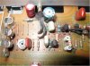
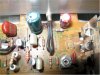
Below are pictures of the 220 ohm resistors (blue body) at R439 and R440.

I hope I have them inserted correctly.
I have the end with the color coding bands facing in as per the originals.

There's a tutorial thread by EchoWars on testing resistors and transistors. Also googled some tutorials on reading the color band codes. Fry's has them packaged by watt/ohms. And they have Semi-conductor/Transistor replacement guides at the racks.

I can't say there is any striking difference in the resistors except after the adjustment it sounds great with Tone Defeat On and Loudness Off. Great 3D imaging.

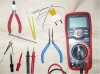
Also pic of some handy tools: Wirecutter (needlenose pliers if you don't have wirecutters), temperature probe, DMM with test probes, small screwdriver, nail clipper for stripping wire (not used here), test clip adapters to connect to test points

Feel free to PM me as you get to a point to start. I can share some tips and steps if I can. Keep in mind this was my first resistor replacement. You're probably more experienced from your speaker repairs.
 

Attachments

  • 220ohmLeft.jpg
    220ohmLeft.jpg
    100.7 KB · Views: 173
  • 220ohmRight.jpg
    220ohmRight.jpg
    178.1 KB · Views: 166
  • tools.jpg
    tools.jpg
    154.6 KB · Views: 103
Bravo terra1 for your courage in this swap!

Large departure from the original design... I appreciate your confidence about my suggestion.

The colour bar orientation is not important, it is a bidirectional device (unlike a diode).

The exact value for the new resistor is not critical, you may replace by a 270, 330 Ohm resistor... Just about anyone you have in your part bins.

By the way, this mod could be beneficial to many other amplifiers and receivers of this family. So, Sir.Byrd, you have two HK to modify! The resistor to change in the receiver may have a different part number (I didn't checked this point) but is at the same position in the schematic.
 
Bravo terra1 for your courage in this swap!

Large departure from the original design... I appreciate your confidence about my suggestion.

The colour bar orientation is not important, it is a bidirectional device (unlike a diode).

The exact value for the new resistor is not critical, you may replace by a 270, 330 Ohm resistor... Just about anyone you have in your part bins.

By the way, this mod could be beneficial to many other amplifiers and receivers of this family. So, Sir.Byrd, you have two HK to modify! The resistor to change in the receiver may have a different part number (I didn't checked this point) but is at the same position in the schematic.

Okay. I'll look into the other one to check it out.
 
Back
Top Bottom