P90
Member
Hi everyone.
I acquired a super-rare NIB un-assembled Heathkit AA-21 amplifier that I just finished assembling moments ago. Being that the kit is so old (even though the box was still sealed), I used new electrolytic capacitors and 1% metal film resistors instead of the originals. I didn't want to chance using the 50+ year old electrolytic caps and carbon resistors that were in the box.
Anyway, I haven't plugged it in yet because the pre-power-on resistance checks are...WRONG.
Resistance at all the test points is about double what it should be. Instructions say +-20% or don't plug it in.
I would really like to plug it in at some point, so...
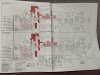
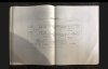
I am uploading the schematic, along with the test points, target resistance, and what I measured at each point.
I'm new to troubleshooting circuitry, but have a great passion to learn and am on a mission to get this thing up and running.
I have a dim bulb tester, variac, Fluke 101, an inexpensive capacitor tester, an old Tektronix scope that typically works on Thursdays and Fridays, an audio function generator app, and an inexpensive TC-1 Multifunction tester for transistors and diodes.
I wanted to use very high res for the schematic, too big to upload, so here's the WeTransfer link to the full-resolution schematic and the resistance test. It expires in a week...
https://we.tl/t-XYet3OOnuO
Thank you in advance for any assistance you care to offer!
Gene
I acquired a super-rare NIB un-assembled Heathkit AA-21 amplifier that I just finished assembling moments ago. Being that the kit is so old (even though the box was still sealed), I used new electrolytic capacitors and 1% metal film resistors instead of the originals. I didn't want to chance using the 50+ year old electrolytic caps and carbon resistors that were in the box.
Anyway, I haven't plugged it in yet because the pre-power-on resistance checks are...WRONG.
Resistance at all the test points is about double what it should be. Instructions say +-20% or don't plug it in.
I would really like to plug it in at some point, so...
I am uploading the schematic, along with the test points, target resistance, and what I measured at each point.
I'm new to troubleshooting circuitry, but have a great passion to learn and am on a mission to get this thing up and running.
I have a dim bulb tester, variac, Fluke 101, an inexpensive capacitor tester, an old Tektronix scope that typically works on Thursdays and Fridays, an audio function generator app, and an inexpensive TC-1 Multifunction tester for transistors and diodes.
I wanted to use very high res for the schematic, too big to upload, so here's the WeTransfer link to the full-resolution schematic and the resistance test. It expires in a week...
https://we.tl/t-XYet3OOnuO
Thank you in advance for any assistance you care to offer!
Gene