• Please note that Audiokarma will be offline briefly for updates early on Monday morning, September 28th.

Heathkit Preamplifier Model WA-P2 Power Supply – What are you using?

tcdriver

AK Subscriber
Subscriber
A Power Supply for the Heathkit Preamplifier Model WA-P2​

The Heathkit WA-P2 is a monophonic vacuum tube preamplifier that was sold in kit form between early 1954 to late 1959. It was designed to complement the Heathkit power amplifiers of that time. The well written manual contains the complete specifications, description of controls, circuit description and assembly instructions. A downloadable manual can be found online. Original copies of the complete manual can often be purchased online from well-known auction websites.

Unlike most modern preamplifiers, the Heathkit WA-P2 does not have a built-in power supply. It was designed to tap its power, from the amplifier it was used with, through an eight-conductor cable terminating in an octal plug. This type of power connection was not uncommon in the early fifties. McIntosh, Dynaco and other manufacturers made preamplifiers that, in a similar fashion, relied on obtaining power from a power amplifier through an umbilical cord. All basic Heathkit amplifiers, of that era, had the proper socket for the power connection. Many other brands of amplifiers could also be adapted to provide the required power.

The easiest way to power a Heathkit WA-P2 preamplifier is to connect it to one of the Heathkit amplifiers, with the proper octal jack. Such a connection will provide the performance of the original design and deliver results that are satisfactory to many music listening enthusiasts.

When an original Heathkit amplifier is unavailable or if improved performance is desired, a standalone power supply is the answer. Finding a ready-built supply, with the right voltage and current capabilities, may not be easy. Oftentimes, one must modify or adapt an existing supply. Sometimes this is very easy and sometimes not so easy. Another option is to build a suitable supply from the ground up.

The power supply requirements are spelled out in the manual. From the Heathkit Preamplifier Model WA-P2 manual (pg. 6):

“POWER SUPPLY:

Requires power from external source, as follows:

6.3V AC at 1.0 amp.

300V DC at 10ma.”

The 6.3V AC supplies the filaments. The 300V DC supplies the B+. The Voltage Chart, on page 32 of the manual, shows the high voltage input specified at 320V DC, which is twenty volts greater than the page 6 requirements. Applying 320V to the first section of the filter capacitor could be a problem for early WA-P2 preamps because the early versions used an electrolytic capacitor with a 300V rating. Later Heathkit WA-P2 units were supplied with capacitors with a 350V rating. Be sure to check which capacitor is in your preamplifier if you intend to power it with a voltage greater than 300V. If you are “recapping”, go with a 350V, or greater voltage, capacitor for the first section. In my power supply designs, I set my target voltage at 320V to be consistent with the Voltage Chart.

Earlier this year, I set out to build a standalone power supply for my Heathkit WA-P2 preamplifier so that I could use it with a power amplifier that did not have a power supply socket. I constructed three power supply versions and tested several sub-circuits before I ended up with my final design. I am offering three design ideas in this thread. What power supply are you using? I would be interested in seeing what others are using for WA-P2 power supplies. Please post them if you have them.

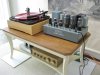
System using a Heathkit WA-P2 with the WAP2PS01 power supply:
PedSys08.JPG
 
Register to hide this ad
WAP2PS01 – First Power Supply

Power supply number one was designed with parts on hand. It is very simple, using back to back filament transformers, two diodes, a few capacitors and a few resistors. This version best resembles the voltages one would see if the preamplifier was connected to one of the Heathkit amplifiers.

The advantage of this supply is that it is simple and straightforward. The disadvantage is that using AC voltage on the filaments which may result in a low level, maybe audible hum, when the high gain microphone / phono stage is used. In this version, the power switch function, located on the preamplifier, is retained.

PS01back.JPG

upload_2016-6-22_21-42-16.png
 
WAP2PS02 – Second Power Supply – Unregulated DC on B+ and Filaments

For the second power supply, I ordered a transformer with both high voltage and filament voltage windings. The B+ supply is a simple diode bridge to a capacitor – resistor – capacitor filter. The low voltage filament supply is a simple full wave bridge to a capacitor – resistor – capacitor filter.

One change was to eliminate the 120V AC voltage going to the power switch in the pre-amp. This keeps any AC voltage out of the preamp and the umbilical cord that connects the power supply to the preamp. A power switch is placed on the power supply chassis to power the preamplifier on and off.

This supply uses a few more parts than the first one and the power transformer was more expensive, however; the results are well worth it in terms of reducing hum from the phono gain stage.

PS-2back.JPG

upload_2016-6-22_21-45-48.png
 
WAP2PS03 – Third Power Supply – Regulated DC Voltage on B+ and Filaments

For the third power supply, I ordered a more suitable transformer. The regulated B+ supply uses a series pass transistor with the other components setting up a high voltage reference for the Gate of the MOSFET. The low voltage filament supply starts with a voltage doubler, which feeds a Switch Mode Power Supply (SMPS) module, that bucks the voltage down to a well-regulated 6.3V DC. As with the second power supply, a power switch is placed on the power supply chassis to power the preamplifier on and off. The line voltage is removed from the umbilical cord going to the preamp.

This supply uses a few more parts than either the first or second power supplies and it takes a little more effort to build, however; it is worth it to have well-regulated supplies.

The Hammond 6K49VG power transformer, used in this example, is less expensive than the Hammond 261G6 transformer used in the second example. The 6K49VG could easily be adapted, with one or two small modifications, to the second circuit.

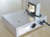
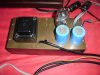
PS03back.JPG

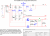
upload_2016-6-22_21-47-32.png

WA-P2 + Power Supply WAP2PS03
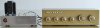
PS03+Pre5.JPG

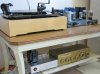
WA-P2 in my music system:
Sys 5.JPG
 
Last edited:
I built a PS for a pair of WA-P2s,,, used a little chassis I had, SS filament supply,, 5V4 rectifier... Turned out very quiet...
 

Attachments

  • P2290019.JPG
    P2290019.JPG
    100.7 KB · Views: 120
Updated power supply WAP2PS03b:
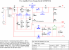
upload_2016-6-30_17-42-27.png
This is the WAP2PS03b. There are a few changes compared to the WAP2PS03. The SMPS is now a MP1584, the reference is a LT1004-1.2 and a variable resistor is now used to set the output voltage.
 
I built a PS for a pair of WA-P2s,,, used a little chassis I had, SS filament supply,, 5V4 rectifier... Turned out very quiet...
This is exactly what I need to do. I have a transformer from a dynaco fm3 that I can use, but I've read that it may only be 280v. I'll have to take some readings myself.
Do you still use this setup? I'm really looking forward to having separate preamps with my monoblocks
 
This is exactly what I need to do. I have a transformer from a dynaco fm3 that I can use, but I've read that it may only be 280v. I'll have to take some readings myself.
Do you still use this setup? I'm really looking forward to having separate preamps with my monoblocks
The Dynaco transformer should work just fine if you use silicon diodes, as I have shown in my schematics. There will be less voltage drop across silicon diodes, than the tube rectifier, which will yield a higher B+ than the +285V shown in the FM-3 schematic. Today's line voltage is higher than the 117V typical of the time the Dynaco was designed.
 
Last edited:
The Dynaco transformer should work just fine if you use silicon diodes as I have shown in my schematics. There will be a lot less voltage drop across silicon diodes which will yield a higher B+ than the +285V shown in the FM-3 schematic. That and the fact that today's line voltage voltage is higher than the 117V typical of the time the Dynaco was designed will also work in your favor.
Good to know. Thanks! I'll see what I have lying around. Debating on whether I add 2 sockets or just wire them directly into the chassis.
I like the idea of a SS rectifier.
Do you happen to have picture of the wiring? I just like to see for ideas of anything else may need
 
Pardon me if it's unrelated, but when I built my last batch of power amplifiers I included an octal socket with which to use an un-powered preamplifier of your choice. I don't own a Heathkit wa p2, but if I came across one I could have my amplifiers adapted to it in an hours time.
I've got a similar style preamplifier in my McIntosh C8+C8s set. That's why I built in the moocher sockets in the first place.
20240212_165545.jpg
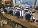
Here they are, you can clearly see on the business end octal em there's an octal plug for a preamp.
Good work,
Carry on.
 
Pardon me if it's unrelated, but when I built my last batch of power amplifiers I included an octal socket with which to use an un-powered preamplifier of your choice. I don't own a Heathkit wa p2, but if I came across one I could have my amplifiers adapted to it in an hours time.
I've got a similar style preamplifier in my McIntosh C8+C8s set. That's why I built in the moocher sockets in the first place.
View attachment 3181078
Here they are, you can clearly see on the business end octal em there's an octal plug for a preamp.
Good work,
Carry on.
I recently recapped and repurposed these for a stereo setup. I have thought about doing the same thing, I just worry that it may be too much stress on the transformer.

It might be worth attempting though. I saw a listing on reverb with somebody that had done exactly that.

The plus is that you can turn the amps on from the tuner.

I'm probably going to give it a try unless anybody advises against it.


4I497Gv.jpeg
 
Good to know. Thanks! I'll see what I have lying around. Debating on whether I add 2 sockets or just wire them directly into the chassis.
I like the idea of a SS rectifier.
Do you happen to have picture of the wiring? I just like to see for ideas of anything else may need
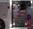
View of the WAP2PS03b insides.
1713630422374.jpeg
 
Do you still use this setup?
Sorry,, I was away this weekend, just got back this afternoon,,, I gave the WA-P2s to a buddy along with the PS last christmas,,,
Here's the thread from a while ago when I got the first one...

 
I'm still learning so go easy on me
I finally measured the secondary on a transformer I had lying around and it's 275-0-275 with 70 ohms between center tap and each lead.
In my schematic that I made with PSUD2 it reads 45, I read somewhere that you should use the calculated resistance but if that's not the case I can change it.
Does this look okay, or how much tweaking should I be doing?
NWXEZ3s.png
 
you can use the calculator in PSUD to figure out the source impedance, it will ask you for AC in and out, and DC resistance of the primary and secondary, but honestly for this its not super important. The current load will be steady. The source impedance is really only a significant factor if the current demand changes by a fair amount, or you have some concern about peak current on a rectifier. With this there is so much resistance between the transformer and the load that the transformer's impedance is not enough to care about.

might want to add a delay of a few seconds so everything charges up. That will give a more useful picture of the ripple. Might also consider changing the load from a resistor to a constant current type. Won't matter all that much really but its a bit more like what it will actually be dealing with.
 
you can use the calculator in PSUD to figure out the source impedance, it will ask you for AC in and out, and DC resistance of the primary and secondary, but honestly for this its not super important. The current load will be steady. The source impedance is really only a significant factor if the current demand changes by a fair amount, or you have some concern about peak current on a rectifier. With this there is so much resistance between the transformer and the load that the transformer's impedance is not enough to care about.

might want to add a delay of a few seconds so everything charges up. That will give a more useful picture of the ripple. Might also consider changing the load from a resistor to a constant current type. Won't matter all that much really but its a bit more like what it will actually be dealing with.
Here's an updated one. Added a few seconds delay and changed C3 to a 40u

Z2Bhgg8.png
 
Back
Top Bottom