• The move to the new server is done. There are some software and database maintenance updates in process. This has us passing the hat around to help out. We appreciate any donations. Seriously, even a dollar helps. The payment page may be found here - https://www.audiokarma.org/support.html

Heathkit W5m delay timer

The thread also has a lot of discussion on what if any delay is needed to cover heaters, and if heater warm up needs to be smoothed. The anecdotal comments I've come across from many forums over the years, from many who have lengthy experience/exposure to commercial grade valve equipment in either service or professional or hobby environments, indicates that valve heater failure rates are insignificant in the context of equipment with failed valves. This also includes from heater flash, which appears to be related to manufacturing process and subsequent tolerances, rather than a design intent. Anecdotal comments are prone to misinterpretation, perhaps as many failed valves were not really checked for cause of failure (ie. swap it, and discard if 'bad'), and very few people had exposure to a statistically large sample of the same equipment from cradle to grave.

Yes, but the problem has, again, multiple facets:
(1) We don't know the heater failure rate in consumer goods, but we do know that the large-scale users of the same tubes used in audio reported high failure rates from on-off cycling.
(2) We know boiling off tungsten and plating onto other tube structures shortens lifespan.
(3) We know the effect of overheating portions of the cathode bakes out the oxide and kills the cathode over time.

Only one referenced paper known of publicly identifies a heater related failure statistic, and that is in a non-commercial equipment environment. Interpretation of special equipment environments such as the Whirlwind Project may be prone to misinterpretation when relating statistics to commercial equipment, perhaps due to the use of special valve types and batches, and different powering. Interpretation of those projects is also prone to poor statistical data availability - even the known paper presents a failure rate of 3.6% which appears to me to be ambiguous (it could be the rate for no special heater warm up, or with special warm up).

It's a pile of tubes which failed a lot less when it was left on all the time. That's pretty convincing.

This was a well-known problem and I have other papers which I will cite. (When I was in grad school this was called "proof by forthcoming paper". At the same time, I really can't be putting all of my research out there at this point. Too many hours, emails, and phone calls to assemble it.)

Discussion by Retrovert is obviously well intentioned, however a continual use of emotive words to assert a view, or reason a proof, could easily make some believe that all valve equipment needs to be modified to some better modern standard to achieve tangible improvement in reliability of their vintage equipment.

Ummmm, "emotive words" such as what? This is a strawman distraction from the arguments I made. Refute the hypotheses and facts presented, not the language used to present them.

I do believe existing equipment should be retrofitted in a number of ways which I outlined, and made no secret of that. I will be doing this in my own amplifiers and other tube equipment. I do believe that respecting the tube datasheets and accepted design practices for reliability is a good idea. Is that too emotive?

Imho, there are lots of subtle changes that can be made to vintage equipment to improve reliability from a whole range of failure situations. Even the inclusion of an AC side thermistor to benefit other issues can alleviate the peak current experienced by tube heaters.

Yes, of course. I specifically addressed inrush current. But this is just one piece of a number of changes.
 
Not exactly to the heater warm up discussion, but similar in that the lifespan issue is addressed. The Bendix red bank tube specs always gives an expected life span under different operating conditions. Red bank tubes were expected to have a lifespan of 10,000 hours when the specified operating conditions were followed. In the chart on "Effect on life of increased ratings" the first parameter addressed is heater voltage. With ratings of "conservative + or - 2%, typical +or - 5% , and maximum + or - 10%" which breaks down to an expected life span of 10,000, 5000, and 3000 hours respectively. The chart shows how critical to tube life expectancy is maintaining something which most amp owners even know of the equipment they operate. And as was discussed previously, it is a fallacy to assume that the manufacturer has your interests at heart when they would like nothing better than to sell you a new set of tubes in 1000 hours of playing time.
 
To tc's question, turn-off pulses are just as destructive as turn-on pulses are. Power supplies with massive reserves of capacitance in NFB designs are particularly prone to them, and they occur moments after turn-off as the cathode is cooling down. Again, this is very destructive to the tubes. My ultimate answer to the question of B+ delay is to (just as with equipment pieces themselves) "stage" the application of B+: Small signal stages are first to get the B+ applied, and the output stage the last. At turn off, the output stage is immediately disconnected from B+ (relay contacts after the PS caps) at the instant of shut down. With this approach, all turn-on and turn-off pulses are eliminated in the output stage. This, coupled with the use of Screen Stability resistors and operating the heaters at precisely 6.30 vdc (slow start with regulation) produced the significant increase in output tube life expectancy that I observed. ...
OK, thank you for the explanation. In review of what is being suggested here:

At power up:

1) slowly ramp up the filaments. Once they reach the correct voltage, then:

2) slowly power ramp up the B+ (or "stage" the application of B+)

At power down:

3) disconnect the B+ (or slowly ramp it down to 0V). Once the B+ is disconnected or 0V, then:

4) slowly ramp down the filaments

So, if that is the goal, I am thinking of how that could be implemented? In one example, one could have a variable power supply, for the filaments, that one could manually, slowly turn up to the correct voltage and then with a second supply, for the B+, slowly, manually bring up the B+. The reverse for turn off. Switch off the B+ or slowly turn it down to 0V and then slowly manually decrease the filament supply to 0V.

Dave, in you example where at power off the relay disconnects the B+, when does that relay get turned on during the startup process? Do you turn on the relay and then ramp up the B+ in stages? In your design, do you slowly ramp up the filament voltages before you start applying the B+?
 
Not exactly to the heater warm up discussion, but similar in that the lifespan issue is addressed. The Bendix red bank tube specs always gives an expected life span under different operating conditions. Red bank tubes were expected to have a lifespan of 10,000 hours when the specified operating conditions were followed. In the chart on "Effect on life of increased ratings" the first parameter addressed is heater voltage. With ratings of "conservative + or - 2%, typical +or - 5% , and maximum + or - 10%" which breaks down to an expected life span of 10,000, 5000, and 3000 hours respectively. The chart shows how critical to tube life expectancy is maintaining something which most amp owners even know of the equipment they operate.

Yes! Excellent point!

Bendix, like other manufacturers, did a lot of systematic work on tube reliability in the 1950s. In this case it was because Bendix provided tubes to the military. I've read military reports which reference these cautions. The warnings were very clear and the consequences were unequivocally stated, yet they were so often ignored because of carelessness, cost-cutting, and general ignorance. We then saw the same problem with transistor circuits that needlessly blew up. I have a few amps from the 1960s which need some minor re-design, such as adding emitter resistors, to spare the output transistors from oscillation and damage. Interestingly enough, I have other amps from the same period which included them.

I have read cautions from the early 1930s about how variations in heater voltage were damaging tubes. It was a well-known problem.

You are correct that most tube-equipment owners have no understanding about their equipment, or the dramatic effects that small variations may have. This is why I say people were conditioned to expect tubes to fail and be replaced, instead of asking the all-important question: why does this happen?

And as was discussed previously, it is a fallacy to assume that the manufacturer has your interests at heart when they would like nothing better than to sell you a new set of tubes in 1000 hours of playing time.

Oh, yeah. True that.

To be fair, though, it's more the equipment manufacturer, not the tube manufacturer. Many of the limits are clearly published in the datasheets (like heater-to-cathode limits, screen and grid dissipation limits, etc.), just not put in a black box like the FDA requires. I think it's more the case that no matter what a manufacturer publishers, it will be ignored by the designers.

I do know of one current tube manufacturer which specifically warns about bad design practices which will damage output tubes and shorten their lifespan. When tubes blow up the tube manufacturer is being blamed as the obvious problem, not the amplifier designer.
 
At power up:
1) slowly ramp up the filaments. Once they reach the correct voltage, then:
2) slowly power ramp up the B+ (or "stage" the application of B+)

At power down:
3) disconnect the B+ (or slowly ramp it down to 0V). Once the B+ is disconnected or 0V, then:
4) slowly ramp down the filaments

With one more addition:
1.5) move the grids and screens such that the tube is in cutoff.
2.5) back the grids and screens out of cutoff to normal operation

At power down:
Prior to (3) move the grids and screens such that the tube is in cutoff.

It is very important that no current flow when the heaters are not fully hot or when B+ is not yet fully powered up. It is equally important that the grid and screen never be positive to the cathode or current will flow.

I think it would be better to put the grids and screen into cutoff before anything is done to turn power on/off, but I'd have to think about the exact point to be sure.

Remember, Subclass 2 is bad for audio, since it has grid current flow, but ok for RF transmitter tubes which are designed for grid current, having heatsinks on the grid. Current flow to the grid or screen heats it, and since this is a fine wire it is easily damaged.

Again, another mode of tube failure is grid or screen failure from overheating or arcing, but this is not typically analyzed by owners of consumer electronics.

So, if that is the goal, I am thinking of how that could be implemented? In one example, one could have a variable power supply, for the filaments, that one could manually, slowly turn up to the correct voltage and then with a second supply, for the B+, slowly, manually bring up the B+. The reverse for turn off. Switch off the B+ or slowly turn it down to 0V and then slowly manually decrease the filament supply to 0V.

Not so hard. Remember, we can use a MOSFET as a switch. So we can just switch the grids and screens into cutoff using a MOSFET.

For ramping the voltage, a MOSFET can be used as a variable resistor. Just feed it a linear RC voltage or a sawtooth or anything else and it basically does what you want. The MOSFET may not always be the most linear of devices when used this way, but for what we want it is perfect.

Dave, in you example where at power off the relay disconnects the B+, when does that relay get turned on during the startup process? Do you turn on the relay and then ramp up the B+ in stages? In your design, do you slowly ramp up the filament voltages before you start applying the B+?

B+ cannot be safely switched with a relay because high-voltage DC will arc. When those contacts open it will arc across them, damaging the relay, including pitting or otherwise ruining the contacts, perhaps even welding the contacts shut, etc. An AC arc tends to self-extinguish at (or very near) the zero crossing. DC doesn't do that. Arcs are easy to start, hard to stop.

Look at the DC specifications for a relay vs the AC specifications. Considerable difference!
 
No. I previously addressed this. It arises because of either a dissimilar material from the weld: "A cold heater is a dead short. Portions, usually the ends because of welds to dissimilar metals..." or because the wire is damaged in some region. Welding will do that.

When spot heating occurs inside the cathode sleeve it is invisible because it is covered. My research into filaments for light bulbs suggests it occurs at any thinner spot in the wire and these hot spots arise because of the manufacturing techniques.

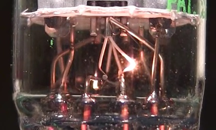
This video clearly shows the origin of the flash is in the length of uncoated filament between the pinout weld and the coated section. To me, it does not appear to be concentrated in one tiny spot (relatively speaking ) as if there were a damaged area. Instead, at the midpoint between two heat sinks, so to speak.

Roughly 4 min 3 seconds in.

 
Although that tech tips video is just one sample, it does suggest the level of manufacturing 'tolerance' that can occur (ie. one heater has negligible bare filament, whereas the other heater has obviously substantial bare filament).

As I see it, heater flash appears to be related to the length of uncoated filament wire between the pin terminal and where the coating starts on the filament. Manufacturing tolerance of wire diameter, length of uncoated filament, and possibly the choice of wire type (ie. temp coeff of the filament) may influence the degree of flash.

The filament current starts with a peak that then drops as the total filament resistance increases. The flash occurs during the first few seconds of applied voltage, when the current is relatively high (but decreasing).

Alumina coated filament has higher thermal mass than bare filament, so initially increases in temperature at a slower rate than uncoated filament.

As the uncoated filament rises in temperature, it cools by radiation to an effectively constant ambient temperature. The radiation transfer increases dramatically for the uncoated wire as it approaches incandescence, due to the rate being proportional to Temp to the power of 4. The reducing current, along with the increasing temperature and hence thermal transfer results in the filament temperature peaking and then subsiding within a few seconds.

Given the low number of flash events (cold turn-ons) in service life, the ability of the wire to operate at incandescent temperatures, and that normal operating temp is well below incandescence, then heater failure from that situation is anecdotally a rare event, and probably related to the small percentage of the population that are at the extremity of one side of a likely bell curve.

If there was a comparison made with the common incandescent bulb, then it would markedly differ in that the tungsten wire sublimation during operating hours would be substantially less in a valve, and so bulb failure during turn on would be substantially less as the wire thickness was not being significantly eaten away over service lifetime.

Edit: link to image of flash as it is subsiding - showing the location of hottest region of filament.
Heater%202a.jpg
 
Last edited:
This video clearly shows the origin of the flash is in the length of uncoated filament between the pinout weld and the coated section. To me, it does not appear to be concentrated in one tiny spot (relatively speaking ) as if there were a damaged area. Instead, at the midpoint between two heat sinks, so to speak.

Sigh. Yes, I am familiar with this video and Carlson's excellent work documenting this problem and his simple solution (run with limited current via a resistor until the filament is hot then use a MOSFET to switch to unrestricted current).

The heater flash clearly occurs at the welds. Carlson even noted this. What is your point? That the coating prevents it? No, that's wrong.

It isn't that the problem is prevented by the heater coating, it is that the structure of the tungsten has been deformed and altered by the welds and is thus more prone to overheating probably, because the tungsten may be thinner there or be an alloy with even worse properties or both.

Making tungsten involves a difficult process of swaging and drawing, and the resulting structure is fragile and prone to damage. Tungsten is a brittle metal whose working is difficult, which is why it is primarily sintered. The Larson-Miller relation explains how the grain size alters and the filament elongates during heating and this, beyond the problems from simple metallurgy, is exacerbating problems at that weld junction.

I've already debunked the idea that a 1 mil coating of a not very good thermal conductor (see below) is going to equilibrate temperature. If you want to support this contention, supply some proof.

Here's my proof. It's called "physics", not "YouTube".

The thermal conductivity (λ) of tungsten is 173 W / (m·K), and for alumina it is about 18 to 35 W / (m·K) depending upon composition. (I just looked it up.) So it would be fair to say that alumina is a poor thermal conductor compared to tungsten. One might even fairly call it something of an insulator compared to tungsten.

So that takes the zombie issue of insulation, cuts off its head, fills its mouth with salt, sews the mouth shut, and then burns the whole mess. Don't resurrect that zombie, it's dead, Jim.

But if you want to keep going at it, you need to explain how something that is maybe 20% (at best) of the thermal conductivity of the metal it insulates is going to equilibrate temperature better than the underlying metal with a thermal conductivity over FIVE TIMES that of its coating? Because I must have missed the lecture in physics that explained this phenomenon. (By the way, some people in Stockholm probably want to give you an award for this discovery. You get dinner and a cool medal.)

While it might appear that only the uncoated regions of the cathode suffer from overheating, the opposite is true and you have no basis for concluding that naked filament is subject to overheating from thermal runaway and that coated tungsten is not. Just because you can't see what is happening underneath the coating or in the regions inside the cathode doesn't mean that the physics are different there. We do know that light bulb filaments, a well studied area, suffer from hot spots from the same swaging and drawing process used for tube filaments, and that it would be reasonable to conclude that tube filaments have identical issues. The companies making tungsten wire for light bulbs made it for tubes.

The coating doesn't prevent thermal problems. It is irrelevant to them. It's a red herring to keep bringing it up.

This is yet another example of the Tinkerbell Effect, which is magical thinking keeps interfering with science. If you want to propose an alternate theory, you need to back it up such that it fits the facts. The one you are proposing does not.
 
Here's my proof. It's called "physics", not "YouTube".

[/QUOTE]

Sigh. Say what you will, the video shows it quite well.
 
Although that tech tips video is just one sample, it does suggest the level of manufacturing 'tolerance' that can occur (ie. one heater has negligible bare filament, whereas the other heater has obviously substantial bare filament).

I was preparing my response while you posted yours.

It isn't tolerance, as I explain above, it is metallurgy. The weld has different composition and is more prone to overheating. Again, this is a disturbance in the tungsten grains and crystalline structure.

As I see it, heater flash appears to be related to the length of uncoated filament wire between the pin terminal and where the coating starts on the filament. Manufacturing tolerance of wire diameter, length of uncoated filament, and possibly the choice of wire type (ie. temp coeff of the filament) may influence the degree of flash.

Metallurgy from the weld. Has NOTHING to do with the coating. See the thermal conductivity explanation above.

Alumina coated filament has higher thermal mass than bare filament, so initially increases in temperature at a slower rate than uncoated filament.

No, that's wrong. Look at the thermal conductivity. The coating doesn't slow down the heating. That's running as a function of current through the wire, and tungsten wire is known to suffer from hotspots as a result of manufacturing issues.

As the uncoated filament rises in temperature, it cools by radiation to an effectively constant ambient temperature. The radiation transfer increases dramatically for the uncoated wire as it approaches incandescence, due to the rate being proportional to Temp to the power of 4. The reducing current, along with the increasing temperature and hence thermal transfer results in the filament temperature peaking and then subsiding within a few seconds.

Ummmmm, that's what I explained. Had you ever heard of the Stefan-Boltzmann Law applied to tube heaters before I wrote about it a few pages back?

Given the low number of flash events (cold turn-ons) in service life, the ability of the wire to operate at incandescent temperatures, and that normal operating temp is well below incandescence, then heater failure from that situation is anecdotally a rare event, and probably related to the small percentage of the population that are at the extremity of one side of a likely bell curve.

I've explained the facts, demonstrating linkage to light bulb effects and large-scale studies. You repeat internet lore without substantiation.

The fact that untrained hobbyists do not understand why their tubes failed, do not perform any analysis of those failures, and do not even report those failures does not, in any way, negate or refute the large-scale studies done for computers and military installations, nor does it negate current practices for RF tubes. Do you have any idea how many tubes the military used in the 1950s? Of course it spent effort to reduce failures and that meant not turning things off.

RF transmitter tubes are not turned off to this very day to prevent this, and it dramatically prolongs their lifespan by years. I posted about orange and black heat. This is not something I made up! It's objective fact.

Cycling the heater damages the tube. Fact.

If there was a comparison made with the common incandescent bulb, then it would markedly differ in that the tungsten wire sublimation during operating hours would be substantially less in a valve, and so bulb failure during turn on would be substantially less as the wire thickness was not being significantly eaten away over service lifetime.

Say what? No it would not.

What do you think that black coating in a light bulb is? It is a thin layer of tungsten boiled off the filament. This is how halogen bulbs work! The halogen redeposits tungsten back onto the filament. Imperfectly, but still redeposits.

The lifespan of any filament is related to its thickness. The thickness of filaments in light bulbs determines their lifespan. Thicker is longer, thinner is shorter. Bulbs fail at turn on for the same reason as heater flash. I've explained this, no sense in repeating it.

Sigh. This is so very tedious. I'm basically done with this as I've explained the facts and the physics, and I see nothing but circular argument.
 
Here's my proof. It's called "physics", not "YouTube".

Sigh. Say what you will, the video shows it quite well.

Hmmm. Let's weigh that. Physics... YouTube... Physics... YouTube....

And the winner is... YouTube!

Except not so much.

You need to substantiate your proposed phenomenon. I've explained the physics in detail as proof that your contention is incorrect. You, in turn, give me YouTube.
 
Hmmm. Let's weigh that. Physics... YouTube... Physics... YouTube....

And the winner is... YouTube!

Except not so much.

You need to substantiate your proposed phenomenon. I've explained the physics in detail as proof that your contention is incorrect. You, in turn, give me YouTube.

Just because it's You Tube doesn't mean it's wrong.

Guess I'm just too stubborn to give in to a "scientific beatdown" when there is something so apparently obvious right in front of the eye, caught on camera.
 
Just because it's You Tube doesn't mean it's wrong.

Guess I'm just too stubborn to give in to a "scientific beatdown" when there is something so apparently obvious right in front of the eye, caught on camera.

I've never before heard physics called a "scientific beatdown".

What is obvious is that you are ignoring the metallurgy at the weld (where the effect occurs) and the physics.

How do you explain away the physics I explained in detail?
 
How do you explain away the physics I explained in detail?

I don't, nor was it ever my point to do so.

I'm simply suggesting the origin of the flash phenoma presents itself quite clearly in the video. And, the point of origin also appears to be coincident with the lowest thermal mass in that vicinity - the unusually long portion of uncoated filament.

Also, if this is predominately weld and heat affected zone, that doesn't seem to explain why the three other filament welds and heat affected zones thereof in the exemplar tube (that in the video) do not exhibit the flash.
 
Quote:

I was elsewhere reading a thread about metal tubes being overheated to the point the paint blistered. That's just really bad design. It shouldn't matter if one can see into a tube, the grid should not be driven positive, and the tube should never be driven this hard.

Retrovert-would this be the post that you are referring to?

I once seriously overloaded a pair of metal 6V6's while ''experimenting'' The smoking and blistering paint was a dead giveaway.....:rflmao:
 
With one more addition:

1.5) move the grids and screens such that the tube is in cutoff.
2.5) back the grids and screens out of cutoff to normal operation

At power down:
Prior to (3) move the grids and screens such that the tube is in cutoff. …

…Not so hard. Remember, we can use a MOSFET as a switch. So we can just switch the grids and screens into cutoff using a MOSFET.
If I understand what you are saying, one could use MOSFETs as switches to pull the grids and screens to a voltage that would cause the tube(s) to be biased in cutoff? If so, do you connect the drain of the MOSFET directly to the grid? How does the capacitance of the MOSFET affect the circuit? Do you choose a MOSFET with low drain capacitance? Which MOSFET, part number, have you used in your amplifiers for this purpose? Is the control to turn on and off the MOSFET a manual control or do you use an automated or a semi-automated control circuit?
 
I don't, nor was it ever my point to do so.

I'm simply suggesting the origin of the flash phenoma presents itself quite clearly in the video. And, the point of origin also appears to be coincident with the lowest thermal mass in that vicinity - the unusually long portion of uncoated filament.

Also, if this is predominately weld and heat affected zone, that doesn't seem to explain why the three other filament welds and heat affected zones thereof in the exemplar tube (that in the video) do not exhibit the flash.

The alumina is a far poorer thermal conductor than the tungsten. It simply can't do what you claim. The physics doesn't allow it. My explanation of the phenomenon is simpler and does not rely on the coating's properties which, if your explanation was correct, would contravene the laws of physics.

The heater flash is at the join to the wires exiting the tube.
 
Quote:

I was elsewhere reading a thread about metal tubes being overheated to the point the paint blistered. That's just really bad design. It shouldn't matter if one can see into a tube, the grid should not be driven positive, and the tube should never be driven this hard.

Retrovert-would this be the post that you are referring to?

I once seriously overloaded a pair of metal 6V6's while ''experimenting'' The smoking and blistering paint was a dead giveaway.....:rflmao:

Retrovert-I'm still waiting for a response.
 
I was elsewhere reading a thread about metal tubes being overheated to the point the paint blistered. That's just really bad design. It shouldn't matter if one can see into a tube, the grid should not be driven positive, and the tube should never be driven this hard.

Retrovert-would this be the post that you are referring to?

Retrovert-I'm still waiting for a response.

Hey, I don't have an AK feed directly into my brain, so you may sometimes wait a while for a reply.

It was about over-driving guitar amps. One area where distortion is valuable and I've been looking into retrofitting mine. I have a pile of metal tube 6V6s of unknown origins and it's tough to tell what's going on in a metal box.

If I misappropriated your paint blistering description as something I remembered as particularly funny and apt, but not the origins of it, my apologies. No slur was intended.
 
Last edited:
Back
Top Bottom