• The move to the new server is done. There are some software and database maintenance updates in process. This has us passing the hat around to help out. We appreciate any donations. Seriously, even a dollar helps. The payment page may be found here - https://www.audiokarma.org/support.html

Help / guidance with fixing up a KA-4002 integrated amp?

Wombaton

Active Member
Dear All,

I have an (originally) non-working KA-4002 unit that I recently recapped following this useful thread:
https://audiokarma.org/forums/index...ist-on-kenwood-ka-4002-integrated-amp.767861/
All of the caps mentioned in the thread BOM (including all old electrolytics), high-stress resistors, trimpots and the diode bridge were replaced. None of the transistors and diodes are replaced yet.

Granted, 'carpet bombing' a dead unit was not a very good idea, but my naive hope was that new components might bring it back to life, plus it was a good training experience anyway.

Here is the current state of affairs: I brought the recapped and cleaned unit up on a variac, using no input sources and using headphones for output. The 'normal / separate' switch was on 'normal.' I found out that on idle the unit is drawing too much current, so I was not able to bring it up to full operating voltage. Per manual, at no signal, power consumption should be <8W, while I got current of above 1A at 40V. At the same voltage, the diode bridge was getting pretty hot. Furthermore, the amp was noisy, with the loudness of the noise increasing as the variac voltage was increasing (the 'volume' control had no effect on the noise level). Just playing it by ear, I got an impression that I am hearing 120 Hz noise (in the headphones). Of course, now I do not know if the problems I see are original to the unit or introduced by me messing with it.

Now, here is my current level of experience: I am Ok with a soldering iron, I can fumble through schematics, but being new to this hobby, I have no experience with troubleshooting things. I have only basic testing equipment: some DMMs, a little electronic components tester (TC-1) and a variac, but no scope / signal generator and etc. Although, I would not mind getting a basic scope (like a USB-based one that works with a laptop), especially if it is going to useful for reviving this amp.

Anyway, I would be most grateful for any advice on how to move forward with testing and trouble shooting the amp. I can provide snapshots of the unit internals on demand. Alternatively, if the combined wisdom says that it is too far gone, that should be Ok as well. Also alternatively, if a more experienced AK-er lives within driving distance and can take a look, that can be arranged in a mutually agreeable fashion (naturally, keeping the current realities in mind).

Regards,

W.
 
Register to hide this ad
Hi everyone. Well let me just say I’m no expert. But I have fixed and restored a handful of KA-2002 and ka-4002. Sounds like you have a dead short. Check your fuse make sure is the correct rating. Check for shorts on the rectifier should not be getting hot that quick. Since you replaced all caps check for polarity make sure you have installed them correctly. Check for solder joint bridges. Check for shorts at the output transistors. You can perform most of this with a multimeter set on continuity and then switch to diode test mode.
 
A DBT is a lot more useful than a variac. Build one and use it before any further damages to the amp.
 
Last edited:
Dear All,

Thank you very much for your comments and advice. I concur with the 'dead short' diagnosis. Some things mentioned in message #3 have been done already, like solder joints, electrolytic caps polarity check and fuses. Since there is a suspicion that this unit might have suffered a violent death in the past, I'd try to go in order of priority when looking for the short. Right now, pulling the output transistors seems like the winner to me. I will try to check them out and report back.

Since I have not messed with output transistors before, some questions about the process:
(1) With all the transistors removed, would it be safe to power the unit on a variac (low voltage)? I assume that normally operating output transistors should be closed / insulating at low input voltage and, therefore, if I still see high current flow with transistors removed, then the short is somewhere else.
(2) Any delicate issues in reattaching the transistors? If anyone can recommend a good generic AK tread about this (choosing and applying thermal paste, etc.), I'd be most grateful.

Finally, I am not clear about the advantages of having a DBT. I can surely build one, e.g., using this article. But the way I read it, DBT is just a poor man's variac / isolation transformer. Of all my equipment, the variac is the most fancy piece worth mentioning -- BK Precision 1655, which can provide immediate info about the current / voltage. So I am not sure why a DBT would be better or safer when testing for shorts. If there is a brief explanation for my own education, I would appreciate that.
 
A variac isn't equivalent to a dim-bulbtester, but each device has its uses, when testing Equipment . ... However, by putting a light bulb in series with your device, it limits the amount of current supplied to your device, thus reducing the risk of damage if there is a power supply problem, etc.
 
A variac isn't equivalent to a dim-bulbtester, but each device has its uses, when testing Equipment . ... However, by putting a light bulb in series with your device, it limits the amount of current supplied to your device, thus reducing the risk of damage if there is a power supply problem, etc.

Well said.
In addition, if there is a short in the amp, DBT takes most of the load so that protects the amp for further damages. It's easy, cheap, quick and effective.
 
Yessir. I only use my variac when ever i get a unit that I know it has not Ben powered for years. To bring it up slowly monitoring the amperage. Or after a restoration testing the unit , when setting bias. Some times it makes me more comfortable using the two combined. But when repairing a known shorted out unit I trust my handy dbt when it passes the dim bulb test then I plug into my variac at full voltage to monitor the repair.
 
After I built a DBT, my variac has little use. Last time I used it with a simple bridge rectifier and caps to reform some NOS caps.
When setting bias for the first time after service, I still use the DBT just to make sure the VR adjusting directions.
 
Limiting the current is far more important that reducing the voltage, which is what a variac does. An incandescent light bulb in series in the hot wire to the transformer in your amp will limit the current going through bad components, and that prevents them from frying. A variac just lowers the voltage and tells you how much current is going through.

If you replaced the main filter caps and didn't put one in backwards or something, most likely you have a shorted output transistor or three, or some shorted zener diodes used for voltage stabilization.

My troubleshooting for that sort of situation would be to check for shorted output transistors, then verify nothing in the power supply is shorted to ground. I would then start checking voltages per the schematic after carefully inspecting for obvious damage -- shorted zeners are often discolored.

Don't forget to check the rectifier diodes too, out of circuit (they usually appear strange in circuit due to the large caps directly connected to them). If you have a 60 or 120 cycle hum, it will certainly originate in the rectifier/main filter cap circuit. Personally, I'd just replace them with higher rated ones on spec, there is no reason not to for the couple bucks it will set you back.

Once you are out of short circuit mode, you can start checking voltages through the amp circuit. Where and how the measured voltage deviates from the specified voltages will tell you which components have failed.
 
Those inexpensive component testers are a great tool for checking transistors since they will usually give you a gain number and a few other characteristics measurements. $20 will set you up nicely.

I also have access to an old in circuit transistor tester. Not always useful as it's quite possible other connected components will cause a transistor to "fail", but it worked great for me. When a transistor tested bad on one channel but the same on in the good channel tested good, it told me either the transistor was bad or something else associated was bad, and helped me track down the bad Darlington "power pack" plus a couple bad driver transistors.
 
Dear All,

Thank you very much for the advice. Needless to say, this site and its inhabitants are a treasure trove of useful information.
I think I know what my next few steps should be -- will start by checking the output transistors and building a DBT.
Special THX for the explanation of different roles of the DBT and a variac in the testing process. I now dig the current limiting capability of the former.

I spent some time educating myself about the process of replacing the output transistors.
As I understand, in case of KA-4002, the original transistors are a TO-66 package.
If they turn out to be fried, the common (and $$$ saving) approach is to replace them with modern equivalents, which are TO-220
and will require special mounting kits, like this one: https://www.digikey.com/product-detail/en/keystone-electronics/4724/36-4724-ND/109792

But from the KA-4002 recapping thread (#93), I see that Fenix479 managed to do just that, which gives me hope :)
One question that I have immediately is this: if I have to go through the trouble of removing the original output transistors, would it make sense to
replace them with modern TO-220 equivalents in any case? Or is it a matter of taste rather than necessity?
The associated costs are modest and the effort is about the same.

THX,

W.
 
I see no reason to replace the outputs unless they are bad. It is not a recommended preventive maintenance action.
 
THX for the input! I would not keep my hopes up about the outputs being healthy in this amp, but will try to preserve the original mica sheets just in case.
Although, for such a modest power amp, I wonder if silicon pads with no heatsink compound would still work (regardless of which TO package I end up using)?
 
I had the KA-5002 amp - cut a lot of lawns saving up for it -- amazed it lasted as long as it did .. the dbt device is not tough to build .. it gave me the confidence to turn on a Fisher 400 ... which I am listenig to now ....
HERE is a nice write up on building a dim bulb tester, with demos
 
THX for the input! I would not keep my hopes up about the outputs being healthy in this amp, but will try to preserve the original mica sheets just in case.
Although, for such a modest power amp, I wonder if silicon pads with no heatsink compound would still work (regardless of which TO package I end up using)?

You can certainly use pads. In that case, no thermal compound...it would have the effect of reducing thermal transfer.
 
We are officially burned!

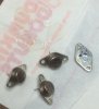
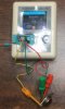
I pulled and checked the original output transistors -- 4x 2SD155 (TO-66). Two checked out fine, i.e., were recognized as 'transistors' by the tester,
and the other two -- not so much. I include some photos, just for fun:

IMG_0563.jpg
IMG_0566.jpg

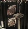
Here I took a photo comparing the size of the 2SD155 transistor to the ones in the KA-5002 amp, which shows how tiny the TO-66 package
actually is relative to TO-3 (as I presume?):
IMG_0704.jpg


Anyway, since now we definitely need replacements, I would be very grateful for any opinions on which of the TO-220 MJE150XX series to use here
and what TO-220 mounting packages could work with them. I was able to find something from Aavid and Keystone Electronics, with the former company
having options with mica and thermasil III silicon pads.
I also found this recent thread on heatsink compounds that people seem to like.

@kappclark: special THX for the DBT construction link -- it is much better than the one I'd originally found.

Regards,

W.
 
Back
Top Bottom