• The move to the new server is done. There are some software and database maintenance updates in process. This has us passing the hat around to help out. We appreciate any donations. Seriously, even a dollar helps. The payment page may be found here - https://www.audiokarma.org/support.html

Help / guidance with fixing up a KA-4002 integrated amp?

@eizner23: Big THX for the link! The price is not bad on these and that should work for preserving the authentic look of the components.
In my case, I am not sure preserving the looks is a priority, especially since the heat sink area on KA-4002 is not highly visible when the cover is on.
Otherwise, a new TO-220 transistor + new silpad or mica sheet still seems to be less than half the cost of the authentic TO-66 replacement.
 
Dear All,
A brief update on the situation. I am expecting my order with new MJE15034G outputs and thermal pads to arrive soon.
Fenix479 has been helping me a lot with details of the output replacement process and other stuff.
I also made a DBT, so I should be all set for the replacement and further testing for shorts.
Will update this thread once I have some results and (as I expect) more questions on what to do next.
With this being my first restoration project, I guess I went off the deep end of the pool.
Regards,
W.
 
We are out of the dead short situation now!

Dear All,

An update on my progress in KA-4002 repairs. I was finally able to put in the new MJE15034G output transistors. This was done with mica sheets and GC Electronics Z9 heat sink compound. Here is how they look like now:

index.php


No continuity between the heat sink and transistor legs. Note that I had to do a lot of scraping and then sanding (down to 2000 grit) of the heat sink in order to remove old thermal compound, which was quite sticky. I wonder if there is a better (chemical?) and not as messy way to do that?

After the new outputs were installed, the amp survived the DBT test. I also checked the current it draws when slowly raising the voltage to 120VAC on the variac. Now it draws very little and is quite stable at that. On the next step, I checked the heatsink / output collector voltages at 30VAC (per service manual instructions on p. 7) and these were significantly lower, compared to the expected values: ~12V on Q2, Q3 (instead of 21V) and ~13V on Q1, Q4 (instead of 42V). Not sure yet what that means -- could this be Ok because the outputs are different type, or is there a problem somewhere else?

Finally, I tried to set the bias current using help from Fenix479 and this thread. From the get go it was clear that the current is too high on both channels: as I was increasing the voltage on the variac, I had to keep adjusting the trimmers to keep the current under control. Also, the heat sink was originally warm on idle at zero volume. Anyhow, I got the R91, R92 voltage below 20mV first, let the amp sit for 10 min to warm up, then did a fine adjustment to ~9.5mV. This setting drifts up and down a little bit, but stays reliably below 10mV at all times. The heat sink remains cold at idle now.

So the amp is out of the 'dead short' regime and I can start checking and fixing other problems. The amp is by far not a happy camper at the moment and has many different noises. Some should be coming from faulty transistors, but the 120 Hz hum that still remains has me worried. It seems to be a power supply problem and I wonder how such noise can leak into the audio path. The next step is to check the voltages per schematic, replace all noisy transistors and refresh diodes. Will see how many problems go away as a result of that.

I would like to thank everyone who contributed to this thread and especially Fenix479 for his invaluable help.

Regards,

W.
 
Last edited:
Time for another update on my KA-4002 revival. Since the last one, I have been consistently replacing semiconductors by their AK community recommended new versions. Would usually replace 2-4 transistors (in matched pairs) and do a sound check. Here is a chronological list of what was done and how it affected the amp performance:

1. Sound check on DBT and variac (headphones) right after replacing output transistors with MJE15034G: amp works and is no longer shorted, but has loud hum [power supply?] and deafening screeching noise [transistors?].

2. Replacements:
Main Amp: Qe9,10 2SC458 --> KSC1845F; Qe11,12 2SC984 --> KSC2690AY; De7,8,9 --> 1N4148
Tone Amp: Qe5,6 2SC458 --> KSC1845F
EQ Amp (RIAA): Qe1,2 2SC458 --> KSC1845F; Qe3,4 2SC871 --> KSC1845F

3. Sound check on DBT and variac (headphones): amp quiet, stable and works well. I figure, replacing Qe5,6 removed most of the noise. Faint humming noise still present, louder when on DBT, much less so when on variac.
Problem: 10-15 min into listening, scratching noise in the right channel. Unaffected by volume/balance. Lasts 2-3 min, then stops. I assumed it may be thermal in nature and checked the radiator, which was fairly warm.

4. Sound check on wall AC (2-way loudspeakers): amp very quiet, stable and works well. Humming noise practically gone.
Problem above remains: same scratching noise in the right channel 10-15 min into the listening session.

5. Replacements:
Main Amp: De1,2 MV-13 --> 2x 1N4148 in series; Qe19 2SC734 --> KSC23830; Qe13,14 2SC1212 --> KSC2690AY; 5T31L thermistors detached from the radiator. Bias current readjusted to spec.

6. Sound check on wall AC (headphones, 2-way and 3-way loudspeakers): amp very quiet and stable. Scratching noise problem in items 3-4 gone.
New problem: amp works well when using headphones. When using loudspeakers: strong distortion in the left channel. High freqs overly bright and full of 'sand.'

Now I am quite confused about the distortion I am getting and wonder what could be wrong? From the schematic, there seems to be no difference between the audio signal hitting the headphone jack or the speakers, except for the signal amplitude, is that right?

I had quite a problem with gain matching KSC2690AY pairs (with my little TC-1 electronic components tester for the lack of a better option), as gain kept fluctuating among multiple measurements of the same transistor. Maybe I went too far replacing the old 2SC1212? Both of these check out alive with hFE ~ 60. The new KSC2690AY that replaced them had hFE ~ 300, but typical values for the batch were ~ 400-440. Could a large gain mismatch in the Qe13,14 pair (i.e., one of these shooting up to 440) be the source of distortion in one channel?

I would appreciate any advice on how to troubleshoot the situation further. Unfortunately, I do not have the (more pricey) equipment to trace the distortion origin, as I assume that a signal generator and a scope would be required. I also feel quite defeated by this first project of mine, as each time I seem to make progress and eliminate one problem, another one immediately arises :(:(:(:(

W.
 
You replaced drivers Qe13,14 2SC1212 with KSC2690AY which is a prefered device in that position. Not all that neccessary to gain match drivers. You would notice other ch not performing well if it was bad substitute selection.

What v reading you get across output .47 emitter resistors on left ch? Outputs hotter than right ch?
 
@eizner23: Thank you very much for your comments. I measured DC voltages across R91 (left) and R92 (right):

1. 'Cold' amp after 20 min idle: R91 ~ 9.4 mV, R92 ~ 12,0 mV; heat sink feels like RT all over the place.
2. After ~40 min playing with headphones: R91 ~ 11-12 mV (oscillating), R92 ~ 12.5 mV; heat sink barely warm, cannot feel any difference between left and right.

Maybe not a representative test for amp loading. I have not built a dummy load yet and my wife objected to testing with loudspeakers (for that evening).
However, the left channel distortion issue does not seem to be T-dependent and shows up at all times.

To everyone: my apologies for posting protracted messages (#24 and #25 are good examples). I am sure no one wants to read through them.
Since I am new in this hobby and not sure which data in truly important, I am trying to keep detailed notes about what I do.

I am usually full of questions after every new working session, but will try to control the madness and ask them in short bursts. Hopefully that will work out better.

THX,

W.
 
Thermistors: their role in the circuit? possible source of noise?

I have a question about the role of thermistors in the main amp. It is applicable to KA-4002, as well as to other Kenwood designs.
Are these components only for protection in case of heat sink / outputs dangerously overheating (and dormant otherwise), or are they actively regulating the current through the amp even in normal operation?
In other words, is it safe to run the amp -- without pushing it too much -- with thermistors permanently disconnected from the heat sink?

The last test I did (message #27) was with thermistors on the sink and the intermittent noise problem (see items 3-4 in message #25) is back, only now it is in the left channel. Are thermistors even supposed to produce 'audible' noise, e.g., if they are aged or degraded?

I am not at all sure they are the problem, since, when using headphones, the heat sink remains barely warm == barely any thermal expansion or resistance change for the thermistors. But apparently, something is still seriously wrong with this amp and it may be beyond my current skills to diagnose.

THX,

W.
 
No idea if this would have a bearing on the situation, but do you have good, functional 10pf caps across the Base and Collector legs of Qe13,14? I was told if these fail, you can have oscillation issues.
 
@ethangsmith: THX for brainstorming! I definitely do have tiny caps in these positions and they look insulating from quick in-circuit testing. Next time I am doing something with this amp, I might remove them to test more carefully.

Not sure when that will be though, as we seem to be a bit low on new ideas in this thread. I may decide to replace the rest of old transistors, but I only got five left to go: Qe15,16 and Qe17,18 on the main amp and Qe20 on the tone amp.

Another idea is for me to find a friend at the university, who has a scope and signal generator in his/her lab, and learn how to trace distortions through the audio tract. Possible, but a bit difficult in the times of COVID.

Cheers,

W.
 
Typically those thermal diodes are on the heat sink to regulate bias current, and if not there, the bias can run away as the amp heats up (the current draw changes with temperature). Put them back and see what happens,

Otherwise, I suspect you have either a bad capacitor (the mica ones will go bad once in a while) or bad transistor you have not replaced, or a bad solder joint. I found that on my KA-80 I had to re-solder a lot of the board to keep it from crackling and dropping the protection relay -- of course, I broke the board too, I'm sure that cracked a pile of them, but on the "twin" KA-80, there were a number that had ring cracks. Worth the time to touch them up and examine your work.

Be especially watchful for loose pads on the board, it's easy to lift them so the don't make good contact. Hairline cracks in the coating are a hint.
 
Last edited:
@HPMguy: thank you very much as well for brainstorming! I appreciate the comment about the thermistors. It would be great to find a datasheet for them to have no doubt about what they are supposed to do, but so far I have been unsuccessful in looking one up for 5T31L. So no idea if it is even a PTC or NTC. At least it seems that materials these are made of (e.g., silicon for PTC) are not typical piezoelectrics or magnetostrictors.

Anyway, it looks like I have a working plan for more upgrades and testing, THX to the thread visitors input: replace remaining transistors, examine the PCB and other areas for cold solder joints, check out 10pf caps on Qe13,14 (drivers). In general, the main PCB foil side quality for my KA-4002 seems to be very high, but this does not mean I cannot have ruined it somewhere already.

Question about Qe20 replacement in the tone amp: just trying to confirm I have the right / recommended one

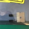
Here is the picture of the original one I got -- 2SC971 with a large cylindrical heat sink:
IMG_0798.jpg

The recommended replacement from this thread is KSC2331 (which I have), but this one has no heat sink:
IMG_0799.jpg

So I wonder if as of today KSC2331 is still the best replacement here?
I tried to double check this and found NTE-192 as a direct replacement. This one indeed has a heat sink, like the original 2SC971. If anyone had experience with this particular batch of transistors, I'd appreciate any insights.

THX,

W.
 
The replacement I put in my KA-4002 also had the large heat sink. I can't remember what it was anymore, but it looked identical to the original.
 
Yup, the absence of a heat sink on KSC2331 got me a little bit worried because the original 2SC971 does get measurably warm when the amp is working. I vaguely remember some posts where people were somewhat critical of NTE products, but if Parts Express sells them, they must be at least passable, right?
Or there may be a different replacement transistor that would work in this position?
 
Dear All,
Another (hopefully brief) update on my KA-4002 restoration project. Over the past week or so, I have been swapping more stuff in and out,
so at present all semiconductors are new:

Qe20 ---> KSC2331 [with no heat sink yet, but the option @eizner23 suggested looks very cool, so I might go for it eventually]
Qe15,16 ---> KSA1220A
Qe17,18 ---> KSC945
De5,6 (1N60) ---> 1N4148 [even if temporarily; have new 1N60P on order]

I also pulled and checked some small capacitors, including the 10pf Ce73,74. All were up to spec, but I replaced them with new caps anyway.
Finally, I checked and resoldered all connections that looked a bit suspicious to eliminate cold joints.

As all these updates were being made, the amp behavior remained the same: works fine with headphones, bur strong distortion (clipping?) in the
left channel when using loudspeakers [does not matter which input or speaker output was used].

However, I found a rather clear symptom of something being wrong in the left channel. Maybe it will be helpful in figuring out what is really going on.
Specifically, after using the amp with speakers, I noticed that Re85 (330R) was getting very hot.
I replaced Re85,86 with new 1/2W metal film and measured the current through them at idle.
Re86 in the right channel (which seems to be working correctly) had ~3.5mA, while Re85 in the left had a whopping 21mA.
At the same time, the current/voltage on the output resistors (0.47R Re91,92) was close to spec (< 10mV).
I have not yet had time to test further (and think about it), but clearly there is a large asymmetry between the channels near Qe15,16.
I figure, the base voltage on Qe15 may be way off, which takes me to the De1/trimpot/thermistor circuit, which is a complete mystery to me.
If you have any thoughts on what I could check next, I would be most grateful.

THX,

W.
 
Back
Top Bottom