• The move to the new server is done. There are some software and database maintenance updates in process. This has us passing the hat around to help out. We appreciate any donations. Seriously, even a dollar helps. The payment page may be found here - https://www.audiokarma.org/support.html

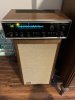
Help me restore my grandfather's beloved SX-770!

Generally its the old electrolytic caps that are an issue. Its actually a paste in there that can dry out over time. The similar vintage SX-1500TD I just restored had two small electrolytic caps on the tone board (3.3 uF) that had blown the bottom seals out. Old tantalums can be an issue too but I don't think this unit would have them. Can use film caps for the smaller electrolytic caps - around 3.3 uF the price starts going up along with the size.

Late 60s up to the mid 70s a number of transistors were used that did not age well, seems Pioneer liked to use a lot of them.

Do one section or board at a time. That way when there is a problem you know where to look. Cap in backwards, transistor in wrong, missed solder joint, bleeding across traces, broken wire, etc. Mistakes will be made, hopefully not often. Here the DBT can be your friend.
I assume the phono channel is considered to be the “Main Amp Unit”? The channel is dead, so that might be a good place to start. Either that, or the power supply wold make sense to me, anyway. I wish I would have done one section at a time on my last project, as that would have saved me lots of time and money...
 
You will know why this is one of the most important pieces of advice only if you don't do it, and need it later. :whip:Mutiple views at different angles of everything! :thumbsup:
Important advice may be an understatement! I learned the value in this when rebuilding the engine in my car. “A picture is worth a thousand dollars in repair bills!” ;)
 
I assume the phono channel is considered to be the “Main Amp Unit”? The channel is dead, so that might be a good place to start. Either that, or the power supply wold make sense to me, anyway. I wish I would have done one section at a time on my last project, as that would have saved me lots of time and money...
The Phono section is a small, very sensitive, specialized frequency response amplifier that takes the signal from the phono cart and feeds it to the Preamp section, that has the source selector switches, volume control, balance control, tape monitors, tone controls, etc. in it. The Preamp section feeds the selected and adjusted signal to the Power Amp, which in a Receiver or Integrated Amp is usually a fixed voltage gain amplifier that has current gain to drive the speakers. The Tuner, whether internal like in a Receiver, or external like an Integrated Amp, is another section that also feeds the Preamp. Lots of people consider the combined internal Preamp and Power Amp to be the "Main Amp Unit" This is my opinion, others may have other opinions. If the amp plays music from the other sources ok the Phono section is (usually) a small problem. :blah:. The possible combinations are endless . . . I like to verify all the power supplies are good before anything else, then dig into the meat, you may have simply lost the power supply to the phono section.
 
Last edited:
Phono preamp section should be the "Head amp unit". Like the SX-1500TD by the schematic the head amp unit should have two each of the Mitsubishi 2SC870 and 2SC871. They should have their classic three diamond symbol on them.

If you have not done it yet, first try cleaning the pots and controls. Relatively easy first step. Have had it bring to life what seemed dead in a number of units, corrosion in one of the pots or switches can kill things. Currently listening to an HK 330C picked up as a fix and repair, any input including tuner just barely audible at max volume with headphones. Sold as having no output. Thought it was going to need replacement components but tried cleaning and lubing all the pots and switches and it now works just fine. That and a couple bulb replacements. Nice to have a working stereo indicator and lit tuning meter and power switch.

The function selector can be a good candidate for something dropping out, one channel or both. Sometimes it has taken more than one cleaning treatment to get one behaving itself. That component has been responsible for dropping channels on several units I have dealt with.
 
Update: cleaning the pots worked incredibly well. After testing, there’s a few residual crackles that will be dealt with in a second wave of cleaning. Parts have been ordered to replace caps and transistors. The replacement transistor thread was a godsend! After doing some research, I opted to go with LED lights, as they shouldn’t cause any flickering issues. I also picked up a multimeter to test components as I replace them. After everything arrives, I’ll be starting with the power supply board. More pictures and updates to come!
 
What do you mean by CEA and CEANL caps? I’m seeing CEMX and CQMA. The ceramic caps look like nice Nichicons and I’m not sure if they need to be replaced. Electrolytics will likely all be replaced.


The Pioneer Tuning Fork series of service guide bulletins/books have a wealth of information from Pioneer about Pioneer specific equipment and general electronics, including what the capacitor acronyms mean ( like CEA and CEANL, etc) in the particular section on capacitors. Browse them or study them, good stuff! Pioneer Tuning Fork Service Guide
 
It’s update time :beerchug:
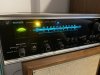
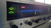
After a second treatment with the QD/F5 combo, lots of the initial problems vanished, as many of you predicted. The Phono channel has fully returned and much of the potentiometer-crackling nonsense has been mitigated as well. I’m blown away at the difference a simple, non-invasive cleaning can make. As seen in the attached pictures, the LED lights are in and look quite nice. Growing up, I always remember this thing having a blank, black face. Seeing the stereo in it’s full capable glory like this was rather special to me, but pretty monumental for my grandfather (at least as far as I can read from a text). He said the lights started to go out one by one in the 80s and never saw them again until now (albeit much brighter than they ever were before). I ordered replacement caps and transistors on Digikey, which should hopefully arrive on Saturday. That’s about all the positive updates I have. I guess I’ll pass the time until Saturday by playing records with the reborn phono channel. :music:
 

Attachments

  • A113C088-FDED-4673-8231-80D5F940D09A.jpeg
    A113C088-FDED-4673-8231-80D5F940D09A.jpeg
    57.9 KB · Views: 71
  • 42BCAB4B-92A7-42BC-8742-DE8EED1F44D7.jpeg
    42BCAB4B-92A7-42BC-8742-DE8EED1F44D7.jpeg
    95.9 KB · Views: 74
Of course, there’s still a few problems to sort out. Here’s what I know at this point:
- The yellow LED light (see pic) for the FM signal indicator is too bright for my liking, and will need to be “creatively dimmed”. It also cuts in and out at random, which leads me to believe there’s a problem further down the line. I’ve tested the diode and resistor with my multimeter and they’re fine. Maybe the recapping and new transistors may fix this?
- Balance pot and high filter button still make popping noises in the right channel. I’ll treat them again when everything is taken apart, although I wonder why only the right channel is affected.
- This unit supports 4 speakers in 3 configurations - “A”, “B”, & “A+B”. B and A+B work fine, but “A” leaves me sitting in silence. Maybe another cleaning will fix this? At least with the A channel working in the third setting, I can assume the A output does work.

When the caps come, I plan on doing a few at a time and checking my work with the DBT. I’ll only do one board at a time as well. I ordered the transistors because they’re really cheap (shipping is not), so they’ll be here if I need them. I didn’t really see any of my transistors on the bad part blacklist, so I’m open to hear what you guys think. Should I replace them anyway, or leave them be? Thanks, AK!
 
- Balance pot and high filter button still make popping noises in the right channel. I’ll treat them again when everything is taken apart, although I wonder why only the right channel is affected.
- This unit supports 4 speakers in 3 configurations - “A”, “B”, & “A+B”. B and A+B work fine, but “A” leaves me sitting in silence. Maybe another cleaning will fix this? At least with the A channel working in the third setting, I can assume the A output does work.

I am suspecting a leaky cap putting dc on the balance pot and high cut switch, either C8 on the Control Amp or C10 on the Main Amp.
The A speakers having no sound on the A position but working on the A+B position just about has to be the switch unless somebody rewired the connection from the A speakers (switch tab) to the B speakers connection inside the unit. Has anybody worked on it before you? It is peculiar that left and right are both silent in the A position.
 
I am suspecting a leaky cap putting dc on the balance pot and high cut switch, either C8 on the Control Amp or C10 on the Main Amp.
The A speakers having no sound on the A position but working on the A+B position just about has to be the switch unless somebody rewired the connection from the A speakers (switch tab) to the B speakers connection inside the unit. Has anybody worked on it before you? It is peculiar that left and right are both silent in the A position.
I was the first one to work on it, so it hasn’t been rewired. I think the switch may just need another cleaning. I’ll take a closer look at the caps you mentioned; that would make sense as to why only the right channel is affected...
 
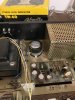
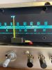
Good progress so far; no issues yet with the recapping process. I definitely lucked out in finding the 3300uF Nichicon cap that fits in the old bracket perfectly. After going through and recapping each board, I’ve been continuing to test with the DBT and then plugging back into my OLAs to hear the differences (probably the only benefit to having the weird speaker wire plugs). I’m using Elna SILMIC II caps almost exclusively, and while they supposedly take about 100 hours of play to reach their full pizazz, I’m already quite happy with the differences I’m hearing after doing each board. In other news, I managed to get the “A” channel working again (it was the knob, as @merlynski said) and even managed to replace the (difficult) little bulb in the tuner needle that seems to have been designed with no intentions of easy replacement down the road... I guess that wasn’t really a priority for Pioneer at the time :dunno:. I’ve included a few more pictures as well. Thanks again for helping me get the ball rolling with this project! Stay tuned for future developments!
 

Attachments

  • 0917842A-4739-4825-BC22-F50EFA353E61.jpeg
    0917842A-4739-4825-BC22-F50EFA353E61.jpeg
    71.3 KB · Views: 68
  • C295F8B1-0E0A-4B07-A706-1B0A2F304BCE.jpeg
    C295F8B1-0E0A-4B07-A706-1B0A2F304BCE.jpeg
    69.3 KB · Views: 65
  • B3198E44-4E43-477A-954E-2B085BFD8BD2.jpeg
    B3198E44-4E43-477A-954E-2B085BFD8BD2.jpeg
    51.7 KB · Views: 61
My pointer was out too. Put in an LED, opened the box, got it to stay in there, reinstalled and wired it in. Unlit it was hard to tell where the pointer was on this thing. In general I don't think pointer bulbs are easy to replace, surgery is a bit delicate on a rather small brittle object. Switched to LED on the lighting, a number of bulbs were out. Looks like yours has the same pointer as mine.

FM died on it a few weeks ago, fortunately someone still had the ECG replacement chip, the new chip has FM stereo back and stereo light is not staying on 100% of the time as before, now behaves as I would expect.
IMG_20200229_013313.jpg
 
Ok, so I'm approaching the finish line with this project, but I've encountered a bit of an issue with the FM stereo indicator lamp.

Basically, I used the lamp that came with the LED kit to relight the pointer in the tuner. The lamp was far too bright for the indicator lamp, but seems to work well so far in the pointer. I have to order a few more things off DigiKey and figured I could just find an amber LED and solder a resistor to it. Measuring the input to the FM stereo indicator lamp, I'm getting 22.2 VDC and 39mA. I'm the furthest thing from an electrical engineer, but that seems like a lot of power to be going to one little lamp. Furthermore, I don't want this new LED to be too bright. If I use this amber LED, what kind of resistor should I attach to the positive lead? Entering the numbers into an online calculator suggested 1000 ohm .5W, but this again seems high to me. I wouldn't even mind spending a few extra bucks getting a few different colors and combinations of various LEDs and resistors to see what works best.

A big headache for a part that costs only 11 cents... :dunno:
 
Ok, so I'm approaching the finish line with this project, but I've encountered a bit of an issue with the FM stereo indicator lamp.

Basically, I used the lamp that came with the LED kit to relight the pointer in the tuner. The lamp was far too bright for the indicator lamp, but seems to work well so far in the pointer. I have to order a few more things off DigiKey and figured I could just find an amber LED and solder a resistor to it. Measuring the input to the FM stereo indicator lamp, I'm getting 22.2 VDC and 39mA. I'm the furthest thing from an electrical engineer, but that seems like a lot of power to be going to one little lamp. Furthermore, I don't want this new LED to be too bright. If I use this amber LED, what kind of resistor should I attach to the positive lead? Entering the numbers into an online calculator suggested 1000 ohm .5W, but this again seems high to me. I wouldn't even mind spending a few extra bucks getting a few different colors and combinations of various LEDs and resistors to see what works best.

A big headache for a part that costs only 11 cents... :dunno:
The schematic shows +19v for the stereo indicator lamp circuit at the Power Supply Ind pin, and 30mA on the other side of the lamp. The resistor inside the Power Supply is 560Ω. With 30mA flowing through it the voltage drop across it is 16.8v. Measure the voltage on the cathode of D4 or D3, it is not marked on the schematic anywhere I can see, but I'm thinking about +24vdc, as the filter cap is rated 25vdc.
Assuming 24v, minus 16.8v leaves 7.2v. Pioneer used a lot of 8v rated incandescent lamps, driven by a slight undervoltage. The schematic implies that the input selector switch is in the AM position, so the stereo lamp would be off. The stereo indicator lamp is driven by an open collector transistor. Here is where it get a bit hazy for me, because I am not a Tuner guy, but it looks like the stronger the stereo signal is, the more the transistor conducts, and the brighter the lamp gets. The brightnes to current ratio of an incandescent bulb is nonlinear, so some current can flow but not be enough to light the bulb. An LED has a very different current to brightness curve, so it may not work well in that position. On AK I have seen people use leds in that application the satisfies them, and I have seen others give up and just put an incandescent bulb back in, because they were not happy with an led. So I don't have a good answer for you, only something to think about. I did look at that led datasheet and it recommends 10 - 30 mA current, with an absolute max of 50mA. My SWAG calculation came up with a 620Ω or 680Ω 1W (standard value) resistor. :blah:

EDIT: The AK go to guy for bulb/led advice is DGWOJO.COM

 
Last edited:
The schematic shows +19v for the stereo indicator lamp circuit at the Power Supply Ind pin, and 30mA on the other side of the lamp. The resistor inside the Power Supply is 560Ω. With 30mA flowing through it the voltage drop across it is 16.8v. Measure the voltage on the cathode of D4 or D3, it is not marked on the schematic anywhere I can see, but I'm thinking about +24vdc, as the filter cap is rated 25vdc.
Assuming 24v, minus 16.8v leaves 7.2v. Pioneer used a lot of 8v rated incandescent lamps, driven by a slight undervoltage. The schematic implies that the input selector switch is in the AM position, so the stereo lamp would be off. The stereo indicator lamp is driven by an open collector transistor. Here is where it get a bit hazy for me, because I am not a Tuner guy, but it looks like the stronger the stereo signal is, the more the transistor conducts, and the brighter the lamp gets. The brightnes to current ratio of an incandescent bulb is nonlinear, so some current can flow but not be enough to light the bulb. An LED has a very different current to brightness curve, so it may not work well in that position. On AK I have seen people use leds in that application the satisfies them, and I have seen others give up and just put an incandescent bulb back in, because they were not happy with an led. So I don't have a good answer for you, only something to think about. I did look at that led datasheet and it recommends 10 - 30 mA current, with an absolute max of 50mA. My SWAG calculation came up with a 620Ω or 680Ω 1W (standard value) resistor. :blah:

EDIT: The AK go to guy for bulb/led advice is DGWOJO.COM
Thanks again, @merlynski . Digi-Key says I'll have the parts in about 3 days. I ordered a few red and a few amber lights and a few different resistor values so I can see what works best. It was pretty hard to find an incandescent replacement that costs as little as the LEDs do. Hopefully it'll play nice with the other LEDs...

I'm hoping to finish up the restoration by this weekend and get everything fully cleaned and buttoned up. Admittedly, I've plugged my speakers into the chassis and have been listening to FM for the past few days in sheer amazement. My generation (early 20's) never really came to fully-appreciate FM, as we tend to think it generally sounds bad. Consequently, it seems that the tuner on this thing is so good that it rivals a direct connection to my phone! I guess the signal itself isn't to blame if it's strong... More pics to come as I finish up the project :thumbsup:

In other news, I had so much fun restoring the SX-770 that I picked up an SX-680 for $30 that came DOA. This one should be a bit more challenging, but that's a topic for another thread... :idea:
 
That is great news. I am probably about your Grandfather's age, when I was your age FM radio was the latest, greatest way to listen to quality new music. Vinyl was common, 8-track tapes were available (but unreliable) and new cassette tape formulations were bleeding edge for portable music. Reel-to-Reel tape was the State-of-the-Art for "Audiophiles." That SX-680 will be a fun project!
 
Update:
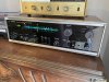
After shipping from Digi-Key was delayed by almost a week, the remaining parts finally arrived and I was able to finish the project. I’m thrilled with the results, as the problems I originally started with were all tackled and the sound is likely better than it ever was, thanks to the Elna SILMIC II caps. The LEDs look pretty impressive in this application as well, behind the black backlit face. With everything complete, the SX-770 will have to live with me until it’s safe to visit my grandparents again — my grandfather can’t wait!
 

Attachments

  • 74E4E886-0477-46A2-AF59-0C0224AC44B0.jpeg
    74E4E886-0477-46A2-AF59-0C0224AC44B0.jpeg
    136.8 KB · Views: 39
Another artifact for those interested:
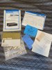
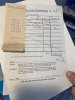
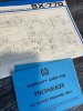
Here’s all of the original paperwork that came with the unit. He’s even kept it all in the original Pioneer bag! The stereo was purchased on August 12, 1971 at the Wiesbaden Audio and Photo Club at the Lindsey Air Station in Germany. He also bought a set of Pioneer CS-33A speakers at the same time and a Technics turntable a few weeks later (I assume after another paycheck came in). He was 20 when he bought this stereo and 50 years later, I finished the restoration at 20, myself. He had this thing longer than my grandmother was in the picture, hence the unit’s tremendous sentimental value. Even for me, this stereo was a huge influence on my musical taste growing up. By the time I came around, the old stereo was relocated to the wood shop. We listened to Crosby, Stills & Nash, The Eagles, Herbie Hancock and all of the other standards from the 60s to the 80s (I’ve since showed him the wonders of Spotify, where he now sports a 5000 song playlist). The main reason this thing was in the wood shop is because it sounded like an actual train wreck whenever the knobs were touched, which my grandmother personally detested... It always had such a nice, warm sound when I was a little kid, though (when you got it going and didn’t touch it). Another fond memory that still lives on today is the volume at which my grandfather listens to things. It was loud when the equipment was off and it was LOUD when he had equipment running. Consequently, my grandmother would be in the kitchen shaking her head. Needless to say, it was pretty cool being a little kid and being around all of this.

Fast forward to the present, and my grandparents have moved into their current house. The stereo was kept as a staple in his new wood shop, although the problems were beginning to outweigh the benefits. The turntable has been out of service for decades and all of the best LPs are in my possession. The pots were scratching so badly and eventually, after years of sawdust exposure, channels started to go. He ended up using a Bose wave system to replace the pioneer, although it continued to grace us with its presence up on the shelf.

I assume he saw something on TV or Facebook about the revival of vinyl, and he had the idea to turn a spare room upstairs into a listening room. He built a shelf for his records and moved everything upstairs. When I came home from college on spring break, he had it hooked up to one of those low end ion usb turntables that were sold around 2008-2010. It skipped around and sounded as you might expect. Since the phono channel was toast, he had it plugged into the auxiliary input and was using the horrendous preamp that’s built into the ion. Surprisingly, the speakers still sounded great, and when they weren’t skipping around, the records would sound pretty good to the average set of ears. Along with the record player, the room has a big table that my grandparents do puzzles on. My grandmother was willing to enter the room as long as nothing was done to make the Pioneer sound like the eruption of Mount St. Helen, although I witnessed her sit through few a few of these “eruptions” during spring break when we were working on putting together a 3000-piece bird-themed puzzle. The eye rolls were there, but they were “loving” eye rolls. She knew they could never get rid of this thing...

At this point, the story picks up at the beginning of this thread — thanks for helping to give it a happy ending!

Once the world calms down a bit, I plan to pick up a nicer turntable for my grandparents and surprise them with a visit. They know it’s finished, but can’t wait to hear it. Until then, they’ll be “puzzling” in silence... :thumbsup:
 

Attachments

  • D087D05D-7952-4284-B05E-09821A25DEF4.jpeg
    D087D05D-7952-4284-B05E-09821A25DEF4.jpeg
    181.8 KB · Views: 32
  • A38521E2-3B06-442E-8EBA-B4D8B536C4F8.jpeg
    A38521E2-3B06-442E-8EBA-B4D8B536C4F8.jpeg
    107.4 KB · Views: 29
  • 8EC633B6-7CD9-4C16-9142-8D57C2881389.jpeg
    8EC633B6-7CD9-4C16-9142-8D57C2881389.jpeg
    142.7 KB · Views: 27
  • 2D66B079-734D-4F69-AC5C-0DDDD293206C.jpeg
    2D66B079-734D-4F69-AC5C-0DDDD293206C.jpeg
    111 KB · Views: 29
Back
Top Bottom