• The move to the new server is done. There are some software and database maintenance updates in process. This has us passing the hat around to help out. We appreciate any donations. Seriously, even a dollar helps. The payment page may be found here - https://www.audiokarma.org/support.html

Help refurbishing Sherwood 7100A

I was able to snag a cheap Sherwood 7100A after reading a ton of positive reviews about it on AK. It has a very weak left channel (seems to be common), so I decided to use that as my motivating factor to replace everything I can for my first project. Although, I've run into a few issues that I need help with.

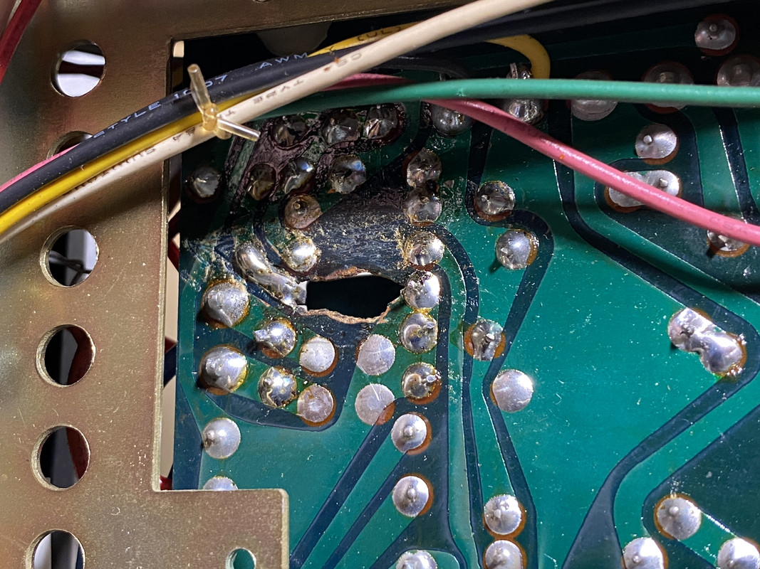
Burnt hole in circuit board

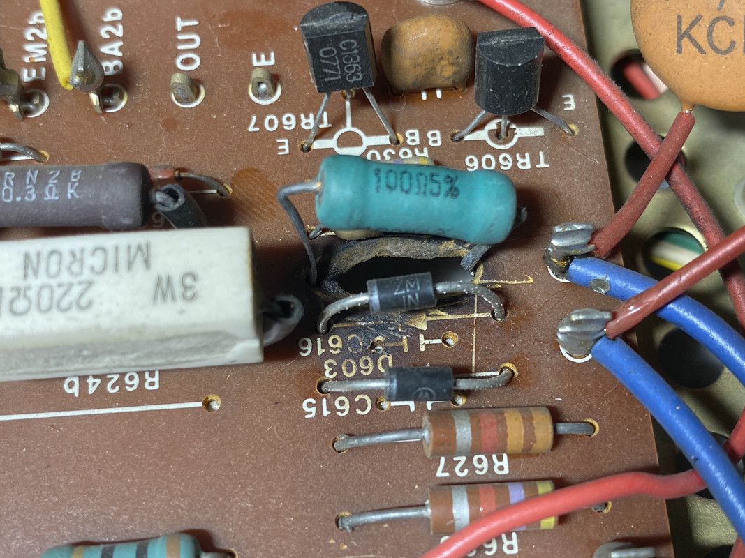
After opening it up, I noticed a hole burnt in the PCB. According to the schematic, this is power supply board territory. Multimeter shows the light blue (don't see another 100ohm one anywhere else) and two bordering resistors are not zero'd out. Unable to test diodes since they're still connected.

Should I be concerned? Any recommendations for improvement?
IMG-6515.jpg

IMG-6515.jpg

IMG-6514.jpg


Sourcing a parts list

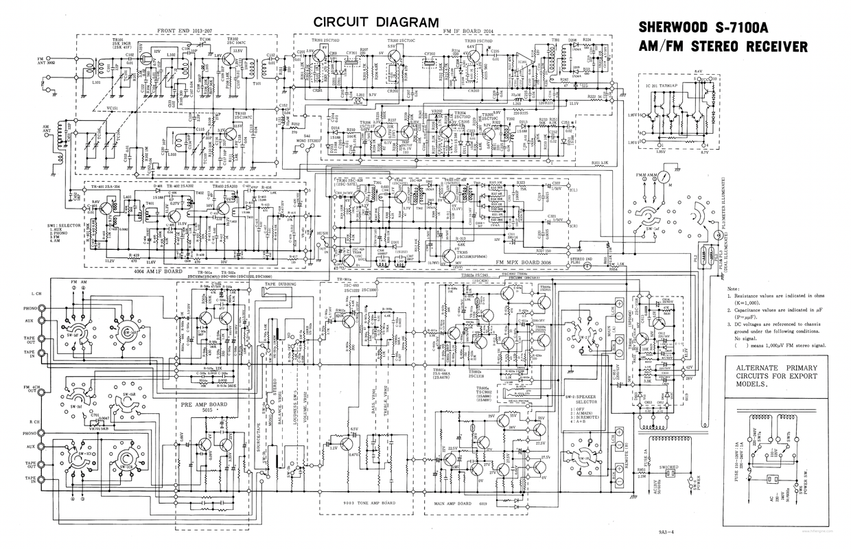
Thanks to a few other threads, I was able to source all the capacitors I need (thanks AK'ers!). Now, I'm trying to identify correct replacements for all the transistors, resistors and diodes that should be updated.

An expert recommended I replace the transistors on the phono board, tone board and tiny ones on the amplifier board but I'm willing to do all of them. Unsure how to approach resistors, have seen some threads on "problematic" ones at a minimum.

I pulled the list of transistors and diodes from the manual, but can't find any list of resistors. Any direction on sourcing the right replacements for everything (including resistors)?

Transistors
2SA202B
2SA203B
2SA354A
2SA666A
2SC693F
2SC710C
2SC710D
2SC711F
2SC828Q
2SC828R
2SC871E
2SC945
2SC1047C
2SC1318Q
2SC1318S
2SD315D
2SK41F
CDC8002C
CDC9002C

Diodes
1N34A
1S188
1S1212
V03C (those neighboring the burnt hole above)
Z-1-12
Screen-Shot-2022-10-17-at-10-22-26-AM.png
 
Register to hide this ad
I am not entirely sure what "zero'd out" means in this context. Maybe that they are not 100% straightly bent and don't keep the original distance to the PCB? If that's the case I don't think this is a reason for concern. Looks to me like that resistor has plenty of space to breathe for the moment. The original resistor probably burned at some point in time leaving the PCB burnt too. Someone most likely has used an abrasive tool like an engraver / dremel or a knife to remove all of the PCB material that turned to carbon to eliminate the short circuit it creates. Afterwards the new resistor was patched on. It's also possible that the heat of the resistor, in case it gets rather warm, over time carbonated the PCB and this may have lead to the resistor failing and burning. I don't really see a problem with this repair if all carbon was indeed removed.
 
I am not entirely sure what "zero'd out" means in this context. Maybe that they are not 100% straightly bent and don't keep the original distance to the PCB? If that's the case I don't think this is a reason for concern. Looks to me like that resistor has plenty of space to breathe for the moment. The original resistor probably burned at some point in time leaving the PCB burnt too. Someone most likely has used an abrasive tool like an engraver / dremel or a knife to remove all of the PCB material that turned to carbon to eliminate the short circuit it creates. Afterwards the new resistor was patched on. It's also possible that the heat of the resistor, in case it gets rather warm, over time carbonated the PCB and this may have lead to the resistor failing and burning. I don't really see a problem with this repair if all carbon was indeed removed.

Hey! I'm new to this, "zero'd" out just means my multimeter showed a reading. That very well may not be an effective way to identify a shorted component.

It's good to know that it doesn't seem like a concern. Should I clean up the bottom with some 99% isopropyl alcohol?

Also I wonder: will this get worse over time? It's possible the new resistor did the trick. If not, I definitely want to prevent any further degradation if possible.
 
  • Appreciate the extremely thorough pics and helpful info. Not always the case here.
  • Testing diodes: To see if they're still good I think a simple continuity check with ohm meter at lowest setting would work. s/b Good if it conducts in one direction but not the other. Diodes are rated in volts and (milli)amps, you list a variety. I think they cross-reference old part numbers with replacement parts if any.
  • Parts sources: The two big go-to suppliers I'm familiar with are DigiKey and Mouser, vast inventory of all types name brand components and good service. There are smaller places and surplus outlets with generally cheaper stuff, watch for quality
Have fun!
 
oh that got toasty. The resistor stuck through the hole is a functional fix but its never going to be pretty. Not really much you can do to make it pretty either honestly. I can't blow the schematic up enough to read and I can't grab a full res copy right now but often when this happens either something failed and caused the resistor to grossly overheat, or in some cases its just really bad design. With that big of a hole, I'm going with something failed in the past and this was the repair. If it was a design problem the replacement resistor would also be pretty cooked looking and it doesn't appear to be so.

My advice here would be to get it working first, replace only what absolutely has to be replaced in order to accomplish that. You can go whole-hog later but I prefer to introduce as few variables as I possibly can when working on stuff. Once it works, then I'll change parts for preventative maintenance reasons.

this may be of use to you

Top Ten Worst Transistors - noisy, failure-prone, whatever... and replacements | Audiokarma Home Audio Stereo Discussion Forums


random other troubleshooting advice, break this into blocks. There may be a block diagram in the service manual but if not, most things are built in a similar way. The phono stage only affects turntable input, so if its weak on one channel only in phono mode, its there. Output of the phono stage, output of the tuner, and the other inputs all feed to the preamp circuit where the tone controls are. Output of that goes to the power amp, output of that to the speaker selector or protect circuit or whatever and eventually to the speakers. The way I usually look for weak channel problems is to see what modes are affected. If its everything, it won't be a fault in the tuner or phono amp. At that point you have to check output of the preamp. If this has pre-out / main in jumpers on the back, thats a handy spot. If not you'll have to find it inside. A scope is damn handy for this but you can do it with a good AC voltmeter too. Input a singal to both channels and measure the amount of signal coming out of the preamp. If its equal on both channels but not equal at the speaker jacks, the problem is in the power amp. If its not equal coming out of the preamp, the problem is there.


now for wild guess speculation time, the last time I had a weak channel in a solid state amp, it was a bad cap in the feedback circuit. Look for an electrolytic cap next to the input transistor that runs to ground. If thats bad, it gets too much feedback and the gain tanks.
 
After some further digging (AK thread here), it seems this resistor is known to overheat in the Sherwood 7100A due to being severely underpowered. It looks like a metal oxide replacement (flame proof) was subbed in and has been operating properly ever since. I'm fine with "ugly," as long as everything works so I feel good about it now. Thanks for the input everyone!

Since I'm using this as my first refurb project, I plan on replacing caps and transistors anyways (for fun and practice!), so I'm confident that should resolve the weak channel issue and ensure everything runs a lot cooler. Will update!
 
Last edited:
  • Appreciate the extremely thorough pics and helpful info. Not always the case here.
  • Testing diodes: To see if they're still good I think a simple continuity check with ohm meter at lowest setting would work. s/b Good if it conducts in one direction but not the other. Diodes are rated in volts and (milli)amps, you list a variety. I think they cross-reference old part numbers with replacement parts if any.
  • Parts sources: The two big go-to suppliers I'm familiar with are DigiKey and Mouser, vast inventory of all types name brand components and good service. There are smaller places and surplus outlets with generally cheaper stuff, watch for quality
Have fun!

Thanks! iPhones make it really easy to grab a few good pics. I always try to be as detailed as possible when asking for help :)

I remember reading that diodes can only be tested when disconnected from the circuit? When I try testing on the boards I get readings both ways for diodes in different places.
 
re: testing diodes. Hmm, I really don't know; it would suggest that testing a diode in place in the (unpowered) circuit would corrupt the reading, or that the diode is "shorted". Hopefully someone more knowledgeable than I will clue us in!
 
@daybreak2350
The problem is that circuits are complex and meters are not smart enough to analyze a circuit. In some cases even trained / educated humans (like me) aren't smart enough for that but I digress. For example if you measure a simple antiparallel diode circuit (two diodes in parallel, in opposite direction) one will always conduct when measured while the other blocks. To be certain it's advisable to take it out of circuit by unsoldering it ot by lifting one leg. PN / NP junctions ("diodes") in a transistor (BJT) are also best measured when the device is out of circuit.

@pioneervibes
It's kind of amazing how good phone cameras have become nowadays.

@gadget73
Good point about the cooked looking resistor in case it would get rather hot.
What we (as a company) did to fix holes in burnt PCBs when we were repairing them professionally was to mask off one side of the PCB with some Tesa clear tape an then fill the hole with epoxy and fibre glass filings. Burnt traces can be fixed by wires or solder wick Sometimes. Depends on the shape of the traces / copper plane. I've also hammered flat some silver wire (tinned copper wire) in the past to fix a broken trace under some IC chip where normal wire wouldn't have worked so well.
 
@LEECH666 comparing to a picture of someone else's unit, I was able to confirm the two black diodes have indeed been replaced as well with 1N629 diodes. I assume they were damaged by the burn.
I don't suspect any other diodes are bad, so probably best to just leave them be right? Replacing diodes and resistors don't seem to be part of a "common update," unless they're suspected/identified to be bad or historically problematic.
 
Yeah that sounds about right to me. Maybe some of the AK gurus can chime in. The question to me is: is the Sherwood working fine atm? Then I wouldn't replace anything besides maybe the common offenders that you've mentioned and that would be it. By far the most common update for a working unit is to replace the capacitors (minus the PSU reservoir caps, the big ones), imo.
 
Last edited:
Yeah that sounds about right to me. Maybe some of the AK gurus can chime in. The question to me is: is the Sherwood working fine atm? Then I wouldn't replace anything besides maybe the common offenders that you've mentioned and that would be it. By far the most common update imo is to replace the capacitors (minus the PSU reservoir caps, the big ones).

Left channel is very weak (common issue). Confident re-cap will fix it. I got it for very cheap, so using as my first "refurb" project. May not need to replace every cap or transistor, but doing it anyways to learn and have fun (and benefit from some modern internals!). Have been able to source the right cap and transistor replacements thanks for AK, so will be off to the races soon.
 
Is there a list of problematic resistors floating around out there that I should take a look at? I thought I saw something before, but can't seem to find it.
 
never seen a specific list, but those old brown square shoulder jobs look like carbon composition, and thats pretty much the entire list of resistors that are known to be problem children. Carbon film or metal film are both quieter and less prone to drift, metal film being the quieter of the two though.
 
never seen a specific list, but those old brown square shoulder jobs look like carbon composition, and thats pretty much the entire list of resistors that are known to be problem children. Carbon film or metal film are both quieter and less prone to drift, metal film being the quieter of the two though.

Just learned that! They're part of the power supply. Had a few AK'ers chime in here saying to leave them be...not sure why? From a quick search many seem to swear by their sound, but everything points to them being pre-disposed to distortion and noise. They were put there for a reason, but assume that's mostly driven by how cheap and available they were 50 years ago...

Metal film seems to be most stable and low temp, so good features for power supply board. Have seen many say carbon film is similar to comp in that there is a warm sound, but not sure that applies to power supply.
 
Adding on:

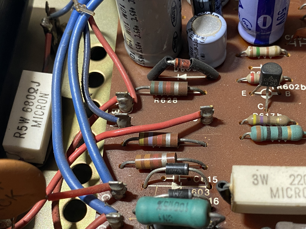
Since this repair was performed before my ownership, I'm more concerned that it was done with the right parts. Soldering seems to be fine but trying to determine if large resistor (100 ohms) and diodes (original V03C) are correct. Best way to find model numbers of the replacement parts to confirm?

Btw, anyone know what kind of resistor this is? Easily dwarfs every other one on my board. Closest visual match I can make online is a metal oxide resistor which have some bulk (like this).
 
Not sure, was going to comment on that earlier but my "swag" (sophisticated wild ass guess) is it could be a wire-wound. It's my understanding that the large ceramic-encased power resistors like the 3 watt in your photo are wire-wound. In rf circuits this can be a concern in that wire-wound can also act as an inductor if in coil form but idk if this presents a problem in audio applications.
Ye ol' carbon resistors can last a very long time but of course heat and material degradation will have a negative effect on lifespan.
The example in your link says "Technology: Metal Oxide".
 
Just learned that! They're part of the power supply. Had a few AK'ers chime in here saying to leave them be...not sure why? From a quick search many seem to swear by their sound, but everything points to them being pre-disposed to distortion and noise. They were put there for a reason, but assume that's mostly driven by how cheap and available they were 50 years ago...

Metal film seems to be most stable and low temp, so good features for power supply board. Have seen many say carbon film is similar to comp in that there is a warm sound, but not sure that applies to power supply.


you shouldn't be "hearing" resistors especially in the power supply. If they aren't off value or causing problems you can leave them be. Any noise they add should be taken care of with the filter caps. Its the stuff on the emitter or collector of the transistors in audio circuits that you are more likely to get noise out of.

I'm not sentimental about old parts, but I'm also cheap and lazy so stuff that isn't currently and isn't likely to cause a problem I leave alone. I also do not care to feel like I'm at the beach on a windy day when trying to listen to music so noisy stuff in the signal chain can go away.


big resistor is wirewound, if you smashed open the ceramic box you'd find a core with wire wound on it, stuck in a box and packed with what is essentially tile grout to hold it all together. They basically work perfectly and stay on value, or they burn open. Not much in between so if its working and not physically falling apart I would leave it be.

unless you mean the blue-green one. That one could be wirewound or metal oxide. Both are common for high power work.
 
big resistor is wirewound, if you smashed open the ceramic box you'd find a core with wire wound on it, stuck in a box and packed with what is essentially tile grout to hold it all together. They basically work perfectly and stay on value, or they burn open. Not much in between so if its working and not physically falling apart I would leave it be.

unless you mean the blue-green one. That one could be wirewound or metal oxide. Both are common for high power work.

Yeah, meant the large blue-green one! I'm probably going to replace it with a modern film equivalent so I know it's right. New one will be much smaller as well.

Still deciding on swapping out the adjacent carbon comp resistors. Would be just fine to leave, but since this is my cheap project I'm in a "might as well" attitude. Why not cover every base so this will last another 50 years.

IMG-6568.jpg
 
Back
Top Bottom