• The move to the new server is done. There are some software and database maintenance updates in process. This has us passing the hat around to help out. We appreciate any donations. Seriously, even a dollar helps. The payment page may be found here - https://www.audiokarma.org/support.html

HH Scott 299D - Power But No Audio

reverend13

AK Subscriber
Subscriber
My apologies in advance as I'm a novice at this yet would love to learn, so I appreciate any feedback :) I have an early-model 299D that powers up and tubes light up, but no sound is coming out of any inputs (also checked cables and speaker connections). I'd appreciate any troubleshooting tips to identify where the breakdown is occurring.

The selenium rectifier was replaced with bridge rectifier GBU6K-BPMS-ND 800V 6A. Since I'm not getting any sound at all, I'm wondering if this ties back to the power section or to the DC balance?

Here are the different measurements I took at 114V --

Rectifier 5AR4
  • Pin 4: 378VAC from PT
  • Pin 6: 379VAC from PT
  • Pin 8: 515VDC -- This seems to be too high. Have used two other rectifier tubes with similar results
  • R211 20 ohm 10W: 515V --> not sure why this is not stepping voltage down since it's a new wire round resistor
  • 30/500 cap to OT: 515V
Bridge Rectifier
  • ~ : - 29.7V
  • ~ : - 29.5V
  • + : to ground 2.57VAC
  • - : - 60.5V
  • R216 10k: - 51.1V
  • C212 to DC Bias: - 51.0V
Power Tube 7591 - V105
  • Pin 3: 515V
  • Pin 4: 42.0V --> should be 410V?
  • Pin 5: .005VAC (0 DC)
  • Pin 6: - 21.1V
  • Pin 8: 42.0V --> should be 410V?
Power Tube 7591 - V104
  • Pin 3: 515V
  • Pin 4: 42.0V
  • Pin 5: .005VAC (0 DC)
  • Pin 6: - 21.6V
  • Pin 8: 42.0V
Power Tube 7591 - V5
  • Pin 3: 515V
  • Pin 4: 41.9V --> should be 410V?
  • Pin 5: .005VAC (0 DC)
  • Pin 6: - 26.9V
  • Pin 8: 41.9V --> should be 410V?
Power Tube 7591 - V4
  • Pin 3: 515V
  • Pin 4: 42.1V --> should be 410V?
  • Pin 5: .005VAC (0 DC)
  • Pin 6: - 26.7V
  • Pin 8: 42.1V --> should be 410V?
6U8 - V103
  • Pin 1: 18.59V --> should be 225V?
  • Pin 2: - .572V
  • Pin 3: 7.85V --> should be 45V?
  • Pin 6: 8.80V --> should be 65V?
  • Pin 7: .118V --> should be 1.3V?
  • Pin 8: 9.10V --> should be 75V?
  • Pin 9: 8.79V --> should be 65V?
6U8 - V3
  • Pin 1: 18.58V --> should this be 225V?
  • Pin 2: - .464V
  • Pin 3: 8.33V --> should this be 45V?
  • Pin 6: 9.22V --> should this be 65V?
  • Pin 7: .105V --> should be 1.3V?
  • Pin 8: 9.43V --> should be 75V?
  • Pin 9: 9.22V --> should be 65V?
Input Tube 12AX7 - V102
  • Pin 1: 22.6V --> should be 170V?
  • Pin 2: - .451V --> looks like this should be 0V. Is this level of DC okay?
  • Pin 3: 0.22V --> should be 1.25V?
  • Pin 6: 22.6V --> should be 170V?
  • Pin 7: - .355V --> looks like should be 0V
  • Pin 8: .024V --> should be 1.25V?
Input Tube 12AX7 - V2
  • Pin 1: 22.8V --> should be 170V?
  • Pin 2: - .357V --> looks like this should be 0V
  • Pin 3: 0.21V --> should be 1.25V?
  • Pin 6: 23.0V --> should be 170V?
  • Pin 7: - .408V --> looks like this should be 0V
  • Pin 8: .018V -> should be 1.25V?
There's been no smoke. Through my research online, since there's no sound at all, does this mean it ties back to issues with the power supply? Maybe there's another capacitor I need to check? When I was using my DMM on power tubes V105 and V104, I could hear the contact being made through the speakers, but not on V5 or V4 -- not sure if this means anything.

I appreciate anyone's help with this as I tried to measure what I could at once. Thanks.
 
Register to hide this ad
You have no significant screen voltage. That means no current will flow, so the DC voltage at the rectifier will be high. It also won't work and none of the voltages beyond the dead resistor will read what they should.

http://hhscott.com/pdf/fs/299D_1.JPG

check R210 and R209. I don't know if one is more likely to fail than the other but I'd bet a nickel one or both are toast. You have plate voltage at the output tube, so R211 is probably fine.
 
You have no significant screen voltage. That means no current will flow, so the DC voltage at the rectifier will be high. It also won't work and none of the voltages beyond the dead resistor will read what they should.

http://hhscott.com/pdf/fs/299D_1.JPG

check R210 and R209. I don't know if one is more likely to fail than the other but I'd bet a nickel one or both are toast. You have plate voltage at the output tube, so R211 is probably fine.

Thanks gadget! I'll double check these tonight as it looks like some of these power resistors (?) may have been replaced at one point in time. R211 and R209 were replaced. Someone also kept the original R209 and maybe used the connections on it as a jumper, despite having also replaced the that resistor (going from memory). I never bothered to check R210 which is the only original out of those 3 resistors.
 
If I'm reading the schematic correctly, it appears R210 is the resistor connected to capacitor can 30/500, 30/500? Looks like the old can was cooked and someone put this in its place.

It looks like it was wired on mine with two resistors in parallel? The DMM readings jump all over the place while checking the resistor unlike the others, so perhaps this one is toast? I have a replacement 30/500, 300/500 can and a 270 ohm 2 watt resistor, so I'm thinking about replacing all that's currently there in the pictures.

I also notice the red wire on the left lost some insulation, and when I pulled it up a bit, there was a section without insulation running along the bottom of the wire against the chassis. Could this be causing a short and killed the resistor?

Thanks,

Scott 30-30-500-500 Cap Can.jpg
Scott 30-30-500-500 Cap Can2.jpg
 
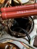
I’m trying to figure out why it looks like there’s a dark hole where the multi-cap can capacitor innards should be. Is it just the lighting angle? Is there anything down in there, like two individual capacitors?
 
I have been working on a lot of HH Scott tube amplifiers lately the LK-48/72, 222 and 299 versions. What I find is that many of the ones which have a lot of hours obvious on them have issues with the first and often the second filter capacitor. Let's face it, they are around 60 years old now. I often just replace them with JJ 32-32 @ 500 capacitors which need a clamp. No, it doesn't look original. But they work very well and I have had no problems with them.

With the Scott amplifiers, slide switches become very problematic. Pots are often scratchy but can be cleaned. And tube sockets are also intermittent even when the tube feels firmly in the socket. I use DeOXIT D5 on the tube pins and and sockets. I scrape the 9-pin tube pins with an X-Acto knife. They are not plated and often corroded, even when they don't look like it. I use a small dental brush to clean the tube socket and have an old tall 9-pin tube that I use to burnish the contacts.

But I can't tell you how many times, slide switches were the problem, to the point of totally interrupting the signal path.
 
I’m trying to figure out why it looks like there’s a dark hole where the multi-cap can capacitor innards should be. Is it just the lighting angle? Is there anything down in there, like two individual capacitors?

it may be restuffed so to speak, with a loose cap inside the hollowed out can

Yes, it's bad lighting, sorry about that. The can was removed at some point. There are individual capacitors sticking out of the hole on the other side of the chassis held together with black electrical tape.

I have been working on a lot of HH Scott tube amplifiers lately the LK-48/72, 222 and 299 versions. What I find is that many of the ones which have a lot of hours obvious on them have issues with the first and often the second filter capacitor. Let's face it, they are around 60 years old now. I often just replace them with JJ 32-32 @ 500 capacitors which need a clamp. No, it doesn't look original. But they work very well and I have had no problems with them.

With the Scott amplifiers, slide switches become very problematic. Pots are often scratchy but can be cleaned. And tube sockets are also intermittent even when the tube feels firmly in the socket. I use DeOXIT D5 on the tube pins and and sockets. I scrape the 9-pin tube pins with an X-Acto knife. They are not plated and often corroded, even when they don't look like it. I use a small dental brush to clean the tube socket and have an old tall 9-pin tube that I use to burnish the contacts.

But I can't tell you how many times, slide switches were the problem, to the point of totally interrupting the signal path.

Thanks for mentioning this. I cleaned all the pins and switches with Deoxit, and after a few times powering on, the amp all of a sudden shut down and wouldn't turn on anymore. This was last week. After going through the power section and seeing the fuse was okay, I was perplexed why it still wouldn't turn on. Cleaned the power switch once again with Deoxit, worked the switch for about a while, now turns on fine. Wondering if the cleaning is enough or if it needs a new switch. Perhaps I didn't clean the other switches enough as well. Thanks also for the tips on cleaning the tube pins and sockets.


Last night I replaced the contraption in the earlier pic with a CE 30-30 @ 500V can, along with a new resistor (R210).
  • Would you replace the remaining 3 capacitor cans as well? Or just the other 30-30 @ 500W capacitor?
  • Perhaps while I'm at it, also replace the capacitors throughout?
  • Would the bare wire without insulation touching the chassis also cause a short or fry anything? I've found a few additional wires where it looks fine looking from overhead, but then lifting the wire shows the insulation split or melted on the bottom facing the chassis. I had to order wire for the voltage (I only had wire that I used for guitar pedals that was rated for 300V).
I feel this is going down a rabbit hole outside of my expertise, even on some fundamental stuff. However, I have some time, willing to learn, and this is a great distraction from work. Really appreciate everyone's help.
 
depends what the wire is connected to. If it was a ground wire, touching the chassis won't do much. If its carrying voltage, then yes it will cause a short in that circuit.
 
depends what the wire is connected to. If it was a ground wire, touching the chassis won't do much. If its carrying voltage, then yes it will cause a short in that circuit.

Thanks for confirming! The red one in the pic is carrying voltage, so I'll redo that one at the very least before powering the unit back on now that I have a new can and new resistor in there. I'll check the other wires carrying voltage to make sure something similar isn't potentially happening.
 
I figured it was a restuff job, what with that unusual circle of wire connected to the can’s ground tabs and the parallel resistors. It’s pretty sloppy work that I’d replace.

When I first got my 299B I replaced all the power supply capacitors. Those are the most likely to cause problems because the electrolyte in them dries out. They are exposed to so much punishing heat and high voltage.

I used to buy replacement cans from CE but with five such cans on the 299B I decided to restuff them all. Those first two get hit the hardest because they’re subjected to a sudden inrush of current and because they’re so close to the hot rectifier tube and all those high wattage power resistors that make these amps great space heaters in winter. I also figure that separate caps, having more exposed surface area, are better at radiating heat than the multiple cap cans that have the dielectrics wound around each other.

The resistors are usually okay though modern versions are often smaller and/or come in an aluminum case that can disperse heat more effectively, especially when fastened to the chassis.

I use 600V or higher Teflon insulated wire that has a much higher melting point than PVC. There’s a guy on Ebay that sells it in ten foot lengths in six or more different colors.
 
C241879E-1351-46B3-816F-9D94952272FC.jpeg
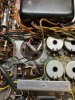
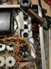
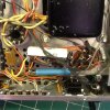
Here’s what I’ve done so far. Replaced the contraption with a can and also replaced the wiring to it. I also went to remove the old power resistor being bypassed and it disintegrated in my hands. As a result, I went ahead and removed the only one that was still working in fears that it was a matter of time before it was also toast.

Would this ohmite be a good replacement? It’s not the kind that fastens to the chassis. I also have some E6000 to keep it in place if needed?

The resistors are usually okay though modern versions are often smaller and/or come in an aluminum case that can disperse heat more effectively, especially when fastened to the chassis.


D506987C-08A7-4FF8-AFE9-A74DB9A02DC5.jpeg
 
Last edited:
That will work, just try to keep it as far away from the cap as possible and make sure it doesn't move around and short on anything. In a perfect world that would be mounted to a terminal strip and wires run to the cap rather than being right on the bottom of the cap to keep it from transmitting heat, but sometimes you can only do so much. You don't exactly have acres of space in there.
 
Put a bolt through it, it'll fasten to the chassis nicely.
Adhesive will adhere for most of one heat cycle one would hope... I'd bolt it Above the chassis, away from the capacitors if possible (not likely)
Use plenty of heat shrink because you'll have prickly voltages above the chassis.

In fact, if you can get brown hollow turd style wire wounds in place of the white brick style ones, I'd put them all 3 above chassis, in a straight line on the same centers as the original.
That much heat should really not be getting dumped inside the chassis in that small area.
 
On my 222C, I put in a couple of terminal strips and positioned those resistors just below the ventilation holes in the chassis. You probably don’t want to put any adhesive on those resistors, they’re going to get pretty hot so any glue would likely melt and put out all sorts of nasty odors.

It’s been some years since I did this job but I’m sure I put in the aluminum cased power resistor on the left to drop the wall outlet voltage a few volts. Unfortunately the markings are difficult to read but I think it might be an 80 Ohm resistor.

F2A5839E-E1B3-4443-BFA7-D6BFA8859B55.jpeg
 
Thanks guys. Noted on the adhesive so will avoid that. These resistors will be close to the PT but not near a cap. I’ll add terminal lugs and debating whether to have them under or on top of the chassis. On top makes sense due to the heat and perhaps why they were originally that way, although my assumption is that newer ones absorb heat much better.
 
Nope. They dont absorb heat.
They create it.
Not any any significant amount more or less than they did in '62, unless your wall voltage is higher than 110 like it was in 1962, which it likely is. In that case they'll likely make more heat. That's what resistors do. They make voltage into heat!
More voltage. More heat.
Under chassis will work, but outside gets rid of heat better.
 
Nope. They dont absorb heat.
They create it.
Not any any significant amount more or less than they did in '62, unless your wall voltage is higher than 110 like it was in 1962, which it likely is. In that case they'll likely make more heat. That's what resistors do. They make voltage into heat!
More voltage. More heat.
Under chassis will work, but outside gets rid of heat better.

Makes sense. Thanks for correcting me on that.
 
Thanks guys. Noted on the adhesive so will avoid that. These resistors will be close to the PT but not near a cap. I’ll add terminal lugs and debating whether to have them under or on top of the chassis. On top makes sense due to the heat and perhaps why they were originally that way, although my assumption is that newer ones absorb heat much better.

I mounted a similar 8K 20 Watt resistor on my LK72 above board, on a terminal strip above the ventilation holes.
I insulated the exposed connections and terminal strip in a piece of large diameter heat shrink tubing and have been happy with the result.
Here's a pic with the rectifier tube removed.
 

Attachments

  • 8K, 20W resistor LK72.JPG
    8K, 20W resistor LK72.JPG
    90.2 KB · Views: 41
One thing to keep in mind is that Scott amplifiers were designed so that there would be no shock hazards above the chassis. All high voltage is below deck. If you mount a resistor above the chassis, the rules have now changed. If you notice a reciever like the Sansui 1000 or 1000A, they have exposed voltages. But they came with a metal cabinet. Scott amplifier cabinets were optional and their equipment was designed to be safe for operation without a cabinet.

Just pointing that out if a resistor is mounted above the chassis. Leads should be well insulated to keep probing fingers safe.
 
Back
Top Bottom