• The move to the new server is done. There are some software and database maintenance updates in process. This has us passing the hat around to help out. We appreciate any donations. Seriously, even a dollar helps. The payment page may be found here - https://www.audiokarma.org/support.html

HH Scott LK-72 rebuild log

carlman14

Member
Hello all! I recently picked up an HH Scott LK-72 with the original manual. It was untested due to the previous owner never getting around to restoring it. From what I've seen, this looks like it's the earliest version of this amp (7199 tubes, no balance pots, two 0.05 uF coupling caps in parallel). This is my first restoration of anything like this, and I'm super excited. I'm creating this thread to log the restoration of this amp, and to ask lots of questions! Here's some info on what I have:

Current state:
  • Had to replace the fuse and busted fuse holder. After that, the amp turned on and I was able to get sound to play through both channels.
  • Front power light works.
  • Bass, treble, and channel balance pots work.
  • There was one joint that was completely unsoldered. Fixed that asap!
  • State of turntable and tape deck (and associated pots upfront) is unknown. I'm mostly interested in the speaker outs.
To do:
  • New tubes (Especially the 12AX7's. They're barely glowing)
  • Replace capacitors. Replace: Ceracaps (orange drop), The coupling caps (two 0.05 uF disc caps in parallel), Top-mounted large caps (https://hayseedhamfest.com/collections/scott/products/h-h-scott-lk-72-re-cap-kit-4-cans)
  • Replace power transformer (Maybe. I heard it's smart to replace the PT in the early versions of this amp with a 299C transformer from heyboer) (https://www.heyboertransformers.com/)
  • Replace bridge rectifier
  • Rewire 7199 sockets to support 6U8A (Identical tube with different pinout. Much cheaper and more plentiful than the 7199). Or buy adapters.
  • Figure out balancing (and potentially add balance pots)
Pre-restoration problems:
  • 60 hz hum in both channels
  • One channel is noticeably worse/weak sounding (bad tubes maybe?)
  • Very scratchy volume pot
Questions:
  • Do I need to replace the disc caps?
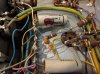
  • There's tons of tiny caps all over the place (At least I think they're caps). Should I replace those too? I took a couple pics to show these.
  • Is this the version of this amp that needs a new power transformer from heyboer (299C I think)?
  • What SS rectifier do I need? Any specs I should look out for?
  • All the caps are marked "MFD" after the value. Is this equivalent to micro farads (uF)? Or is it milli-Farads?
  • How would I add balance pots to this version of this amp? That would be very convenient to have.
  • Is it possible to add bias pots for the output tubes to this version of this amp?
  • Is there anything else that should be done as part of this restoration?
That's all the questions I have for now. I'm sure I'll have more later. I'm going to start ordering parts, and keep this thread updated as I go!

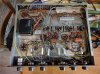
IMG_20201004_114407.jpg
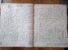
IMG_20201004_114254.jpg
IMG_20201013_102500.jpg
Examples of the tiny caps that are everywhere:
IMG_20201017_150854.jpg

IMG_20201017_150953.jpg
 
Register to hide this ad
I can answer one or two questions. First, MFD = uF as you surmised. I personally would replace all the Ceracaps (the white ones). I'd leave the silver mica(s) alone and I'll let others chime in on the ceramic disc caps. Good luck with the restoration and I'll look forward to your progress reports/pics!
 
Vote number 2 for the removal of the Ceracaps, When I first received my Scott LK48D it sounded
really bad once I changed those caps out it sounded much better, there great amps when restored.
 
agree with what's been said so far...get the ceracaps replaced. little disc caps are probably fine. your call if you want to replace the tone controls and other caps under the control panel.

I have the later version LK-72B so I'm not too familiar with the early version. looks like you have the selenium rectifier so you'll probably want to replace with a silicon type. I used this one: https://www.mouser.com/ProductDetail/vishay/vs-kbpc804pbf/?qs=u%2bh7cTrMUz8Tzzk6wIS4ZA==&countrycode=US&currencycode=USD

hard to read your schematic image, but those two large orange caps on tubes V5 and V6 are polarized? not sure how old they are but they look the part for an original component. hopefully others will chime in about them, but I'd bet you'll want to replace them too. also, can you get your tubes tested?

as for individual balance/bias control, I'm sure it can be done with the addition of cathode resistors and the necessary pots and wiring. My LK-72 had switches and RCA jacks that were pretty easy to modify underneath but still maintain the stock look. I'm betting you'll want test points on the top or back side for access so you'll likely be drilling.

they are wonderful units and you'll enjoy it immensely when finished. very much worth the effort! welcome to AK, carlman!!

-Steve

**oh, and plus one million for the Hayseed Hamfest can caps!!!
 
Last edited:
First, MFD = uF as you surmised. I personally would replace all the Ceracaps (the white ones). I'd leave the silver mica(s) alone and I'll let others chime in on the ceramic disc caps.

Thanks for the input! Appreciate it!

hard to read your schematic image, but those two large orange caps on tubes V5 and V6 are polarized?

Yeah, not sure why my pictures aren't blowing up to full size... but yes, those two caps are polarized and look original.

as for individual balance/bias control, I'm sure it can be done with the addition of cathode resistors and the necessary pots and wiring

This is something I'll probably try to figure out later. I will definitely need more instruction on how to do add these eventually. I'm comfortable with the drilling required, but the circuit changes are what I'll need to do more research on.

oh, and plus one million for the Hayseed Hamfest can caps!!!

I'm happy I found these! Oddly enough, I found hayseed's capacitor listing for the "B" version of this amp, and the caps for that listing perfectly match what's in my "non-B" amp and what's in my instruction manual. Weird... but I'm glad I saw that.
 
I would not proceed with any wholesale replacement of tubes, especially not based on heater glow. The 12AX7s in your amp run with a little over 10V on the heaters so they're not going to be exceptionally bright.
If you can, get the tubes tested by some reputable tech and do your recap and clean controls and tube sockets before thinking about tube replacement unless of course they test bad.
I don't know about the PT either, maybe someone else can give you info on that. That's a pretty expensive component to replace unneccessarily.
Oh yeah, welcome to AK and good luck with your project
 
Hey carlman!

The LK-72 is an excellent amp! Once your done you will be extremely happy with it.

I’m adding the link to my restoration as there was a ton of great advice and guidance given to me and this may help and save you some time. Mine is a little later than yours, 1960, but many of the same things apply to yours.

Enjoy the restoration,!
Glenn
https://audiokarma.org/forums/index.php?threads/my-scott-lk-72-project.614887/
 
I would not proceed with any wholesale replacement of tubes, especially not based on heater glow. The 12AX7s in your amp run with a little over 10V on the heaters so they're not going to be exceptionally bright.
If you can, get the tubes tested by some reputable tech and do your recap and clean controls and tube sockets before thinking about tube replacement unless of course they test bad.
I don't know about the PT either, maybe someone else can give you info on that. That's a pretty expensive component to replace unneccessarily.
Oh yeah, welcome to AK and good luck with your project

Gotcha. I actually already have a replacement tube set. I don't have a convenient way to test the tubes right now, so at least I know I have a new/working set until I can test the originals to see if they're good.

I’m adding the link to my restoration as there was a ton of great advice and guidance given to me and this may help and save you some time.

This is great! Thanks for the link. I've only read through the first page and it's already been useful!
 
If you are getting the correct voltages from the power transformer, and it is not noisy, or getting excessively hot, I would think it is OK to use. If you do have to replace it, send your original to Heyboer
for a rebuild. I ordered some Fisher power transformers from them several months back, without sending my old one to them. What they sent me had to be refitted, was not the correct size, but voltages were correct.
 
Last edited:
When you change out the bridge rectifier, you might have to replace the first resistor in the string to get the -45 VDC at the end of the string indicated on the schematic. Include a few 1 watt metal film or metal oxide resistors in values incrementally above 18 ohms if you’re doing a parts order, unless you already have these on hand.
 
Unless you really want to spend money, I recommend you just replace the can caps and the selenium rectifier. Then check all the voltages out of the power supply, clean up all the tube socket contacts, switches, POT's, and give it a listen. I changed out the Ceracaps on mine, and when I checked them at operating voltage on an EICO 950 all tested fine. No harm in changing them, (and maybe some peace of mind) but it proved not to be necessary on mine. I wouldn't bother converting the 7199's either, especially if you have a pair. They last a long time.
 
If you are getting the correct voltages from the power transformer, and it is not noisy, or getting excessively hot, I would think it is OK to use.

True. I'm mad I can't find that post now, but it was saying that HH Scott released the initial LK-72 units with a PT whose specs weren't quite correct for the amp, and fixed it in subsequent versions. I'll measure all the voltages and make sure they're correct. If so, I should be fine.

When you change out the bridge rectifier, you might have to replace the first resistor in the string to get the -45 VDC at the end of the string indicated on the schematic. Include a few 1 watt metal film or metal oxide resistors in values incrementally above 18 ohms if you’re doing a parts order, unless you already have these on hand.

I was going to ask about that! I've seen that recommended because the silicon rectifiers are more efficient. Silly question, but how would I measure the -45V? Is it measured across that last 18 ohm resistor on the can cap?
 
The -45V is on the schematic. Right before the tube heaters, by V4, across the last cap. It's not across the 18 ohm resistor...
 
Ah, I see. Yep... the selenium rectifier definitely needs replaced. I get -41V across the rectifier itself, and -31V across the last cap.
 
Now check the voltages on the output tubes and see where your at. Pins 3 5 6 and 8.
You'll get it sounding great!
 
Six tubes trying to light themselves up with 31 volts - no wonder they don't look very bright! (In case this isn't clear, HH Scott hooks up the small tube heaters in series, like old fashioned Christmas tree lights, and powers them with the negative voltage that is also used to bias the power tubes.) EDIT: it's actually only four tubes

I would add that it would be really easy, and much cheaper than buying a Hayseed cap can, to duplicate the bias circuit on a tag strip or a little piece of circuit board. Four 100uf/100v radial electrolytics, four 18 ohm 1 watt resistors -- these parts, in modern form are tiny and would only cost a few bucks. Leave the can in place for looks. You could actually do this for all the cap cans in the unit; there is plenty of space under the hood.
 
Last edited:
When I did mine I put the bias caps underneath and left the can. The others were commonly available in either blue or black 32 mfd cans IIRC and I used clamps to hold them. You can see pictures if you search for a thread “Brown faced Scott”
Can’t figure out how to link it on my phone..
 
Now check the voltages on the output tubes and see where your at. Pins 3 5 6 and 8.

Pin 3 (plate): 428V
Pin 5 (grid 3/cathode): 0V
Pin 6 (grid 1): -16V
Pin 8 (grid 2): 401V

From datasheets I'm looking at, I think the plate, grid 1, and grid 3/cathode are all looking good. I'm not sure about grid 2.

I would add that it would be really easy, and much cheaper than buying a Hayseed cap can, to duplicate the bias circuit on a tag strip or a little piece of circuit board.

That would have been really smart... if I hadn't already ordered the hayseed caps. Looks like they're returnable within 30 days. I might just do that!
 
Back
Top Bottom