• The move to the new server is done. There are some software and database maintenance updates in process. This has us passing the hat around to help out. We appreciate any donations. Seriously, even a dollar helps. The payment page may be found here - https://www.audiokarma.org/support.html

How to diagnose frequency response

justinis

Active Member
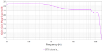
I have a custom built tube amp. Schematic attached. I recently noticed it sounds kindof dead compared to other amps. I made a frequency response measurement of it and sure enough, the gain drops from 25 dB at 200 Hz to 22.5 dB at 10 kHz:
gain.png

How should I begin to diagnose this?

I simulated the entire amplifier in LTSpice. In simulation, the gain is the same at 200 Hz and 10 kHz. However I don't have any parasitics modeled. I am suspicious the problem is related to transformer parasitics. Should I try to model them and produce the rolloff in simulation so I can tweak component values to correct for it? Or is simulation a fool's errand and I should make more measurements of the amp itself to determine where the problem lies?
 

Attachments

Register to hide this ad
I'd suggest actually measuring it to see how it compares to the model. I don't pretend to know the modeling software at all, but unless the specifics of the transformer are very accurately recreated its not going to come out right. Also if the transformers you used are not the same as the amp was designed around, it'll come out different too.
 
Sorry if I wasn't clear: that's what I did. The graph above is an actual frequency response measurement of the amp. The simulation shows a flat frequency response from 200 hz to 10 kHz, not the 2.5 dB drop shown in the measurement.
 
Ah, ok. I thought that was a model.

ok so real response. honestly this is a funky curve to drop like 2.5db from 500 to about 3khz but be flat above and below that. If this were some sort of typical RC filter thing it would have a steady downhill slope. This is the sort of curve you get from putting caps in series with the feedback network like a phono stage or whatever.

Speaking of that, there is no extra cap between the speaker output and the feedback input connection is there? Also, are the values in the feedback network correct?

I do sort of wonder about that AC balance pot. Seems unnecessary and configured in a strange way. I might be tempted to unhook that and see if anything changes.
 
I'm taking a guess, that there may be some mis-labeled or otherwise incorrect value parts in the feedback loop. If those compensation caps are the wrong value (it's easy sometimes, to accidentally wind up with something 10 or 100 times the value, just by mis-reading a number code), that could definitely cause that issue.

Same goes for resistors. I've accidentally read a resistor code upside down, and installed wrong value resistors into an amp- to then wind up going round and round trying to find out why it didn't work right, for hours, until I happened to notice the value error.

Regards,
Gordon.
 
Thanks for the replies! The schematic should match what's in the amp. Unfortunately I cannot check if any parts are "correct" because the amp is one-off custom. But I'm interested that both you guys are pointing to the feedback network. How would I go about determining the best values?
I do sort of wonder about that AC balance pot
Do you mean the volume knob? That and the bias are the only pots. I think it's wired properly.
 
Confirm that the values match what the schematic says they ought to be. Just in case there was a mistake at assembly.


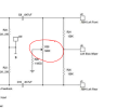
The pot I meant is this one

1767588168690.png

unless thats meant to be DC balance, but I don't see it working well for that either. It just seems like it would allow a lot of signal to cross from inverting to non-inverting and I don't see the point in it. Normally a DC or even AC balance pot done in this manner would have the wiper right to ground, not through a 1M resistor.
 
The design doesn't seem to have much negative feedback. Probably a wonder it's as flat as it is. The shunt in only 100 ohms to ground.
 
Could be a compensation network (shelf/step) kicking in. To me it looks like its critical frequency is more-or-less at 1 KHz and levels out at about 10 KHz. Look for a series combination of a small value capacitor (100 pF or so) with a large-ish value resistor (5k to 10k or so) in series, tied in at the plate of the first stage and connected either to ground or to the HV rail of that stage. To debug this, you may have to temporarily disconnect that step/shelf compensation network and run your tests again to see if it changed anything.

Note there could be an incorrect value in the actual wiring of the shelf/step network relative to what the schematic shows.
 
A sidenote : I see that the bias seems to be regulated. It's contradictonary to stabilaze bias and not stabilazing B+
What happens is that ant mains voltage fluctuations will be exaggurated.
I also note that the schematics is a ripoff of tubes4hifi's vta70. Which does not perform as well as the original.
I suggest rebuild according to Dynaco st70, that eleminates both millereffect sensitive triodes.
 
If I were trying to diagnose it, I would remove C3, C4, C5, C6, R13 and R14, then adjust the value of R9 and R10 until I knew I had a decent amount of feedback, at least 15dB. Then I'd look at a 10kHz square wave and see how bad the ringing is. From there I'd fiddle with C5/6 and R13/14 until the square wave looks reasonable smooth, then play with C3/4 to improve it further. Then you need to check for stability by placing a .1 cap across the dummy load. In a nutshell, you've got to start all over with the feedback and compensation networks and see if you can achieve a flat response and decent stability. Looking at a 10kHz square wave in real time will help you do this.

Unfortunately the links in your blog page are long gone so we can't inspect the sources for this modified clone.
 
A sidenote : I see that the bias seems to be regulated. It's contradictonary to stabilaze bias and not stabilazing B+
What happens is that ant mains voltage fluctuations will be exaggurated.
I also note that the schematics is a ripoff of tubes4hifi's vta70. Which does not perform as well as the original.
I suggest rebuild according to Dynaco st70, that eleminates both millereffect sensitive triodes.
Its not regulated exactly, it appears to be using EFB, referencing the screen supply so the bias will swing with the screen voltage. Its not just fixed to a static voltage.


The driver board looks to be a VTA-derived thing but with different output transformers and output tubes it has little else in common with any ST-70 derivation. I've helped people build very not-Dynaco amps using Dynaco driver boards before. They work pretty well as a sort of universal front end, tailored to fit whatever you want downstream.

were I designing this, I'd have probably gone 6L6GC, and mostly for tube availability reasons. If the driver can kick out enough for an EL34, its enough for a 6L6GC. Transformer load is generally similar between a 7591 and a 6L6CG too.
 
Think EICO ST70, not Dyna. I have seen mismarked mica caps - had a batch of one value when I was working on radio transceivers in the 70s. Easier to deal with than reverse banded diodes, which seemed to be random - the problems that made no sense were usually a solder bridge or backwards diode.
 
yeah you're right, it is a lot closer to the Eico ST-70 circuit. 12au7 in place of the 6sn7, but close enough functionally in an LTP config.
 
yeah you're right, it is a lot closer to the Eico ST-70 circuit. 12au7 in place of the 6sn7, but close enough functionally in an LTP config.

But it's NOT an Eico, because the output transformers are from a Heahkit AA-100, so if Shannon Parks used Eico transformers, then the feedback compensation is going to be way off for this particular build. That's why I suggested he may have start over with the step filter and phase-lead cap. It sure looks like what he's using now is a bad match for the OPTs.
 
Thanks everyone! Sorry for the slow responses; I'm at work today.

The amp uses a ditytube ST70 driver board made by Shannon Parks which is not available anymore, along with the tubes and transformers from a Heathkit AA-100. I have attached the manual for the driver board. When I first did the build years ago, a tube amp guru helped me tweak the feedback/compensation. The values we changed were:

C3, C4 330pF
C5, C6 100pF
R1, R2 7.32K
R7, R8 3.74K
R13, R14 1K

Original values:

C3, C4 220pF
C5, C6 330pF
R1, R2 1K
R7, R8 1K
R13, R14 5.6K

I think zackthedog is right that I should probably start over with tuning the feedback. Let me know if there are any broken links you would like to see; I should have everything.
 

Attachments

Last edited:
Back
Top Bottom