• The move to the new server is done. There are some software and database maintenance updates in process. This has us passing the hat around to help out. We appreciate any donations. Seriously, even a dollar helps. The payment page may be found here - https://www.audiokarma.org/support.html

How to diagnose frequency response

That may slightly improve bottom end response, but it won't alter HF response. Small coupling caps form a voltage divider that varies by frequency, basically the Z or impedance of the cap increases as frequency decreases. Negative feedback will overcome this until it runs out of gain to play with.
 
gain-png.3669159

I have a custom built tube amp. Schematic attached. I recently noticed it sounds kindof dead compared to other amps. I made a frequency response measurement of it and sure enough, the gain drops from 25 dB at 200 Hz to 22.5 dB at 10 kHz.
I know you prolly already addressed this, but high-end clarity and roll off can happen with tired signal tubes. Do you have strong input and gain stage tubes in your unit?

Thanks! :)
 
Well, I found the issue, sortof. As a sanity check, I measured the amp by inputting a sine wave, varying the frequency, and measuring the output. The frequency response is within 0.5 dB from 20 Hz to 20 kHz using this method. When I did the measurement with the Bode 100, I used a 10x scope probe to protect the Bode's input. I think the lack of low frequency compensation on the probe caused the 500 Hz rolloff.

I'm disappointed because now I have no smoking gun. I've been reading about what could cause the "deadness" I hear, or a lack of high end clarity. I can't distinguish different instruments like I can when I listen to my cheap class D solid state amplifiers using the same source and speakers. I read a bit online and some sources point to intermodulation distortion. I've never measured anything but frequency response and stability on this amp. Do you think I should try measuring IMD?
 
Well, I found the issue, sortof. As a sanity check, I measured the amp by inputting a sine wave, varying the frequency, and measuring the output. The frequency response is within 0.5 dB from 20 Hz to 20 kHz using this method. When I did the measurement with the Bode 100, I used a 10x scope probe to protect the Bode's input. I think the lack of low frequency compensation on the probe caused the 500 Hz rolloff.

I'm disappointed because now I have no smoking gun. I've been reading about what could cause the "deadness" I hear, or a lack of high end clarity. I can't distinguish different instruments like I can when I listen to my cheap class D solid state amplifiers using the same source and speakers. I read a bit online and some sources point to intermodulation distortion. I've never measured anything but frequency response and stability on this amp. Do you think I should try measuring IMD?
And these results are with strong testing input-stage and phase-inverter tubes?

Thanks!
 
Last edited:
Yes, brand new ones
I've had a few brand new ones test poorly. Where did you buy them from?

I'm asking because, in my opinion, with the symptoms of sudden bass roll off and poor transient response, you need to first rule out any tube issues. At least before doing surgery on the circuit.

Do you have any other good testing tubes you can substitute?

Thanks!
 
so do we have a current, accurate frequency response plot, and a schematic with in-circuit voltages on it?

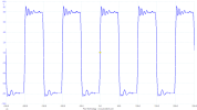
Also any chance we have square wave responses at 10khz?

Whats the measured global negative feedback level?

whats the current setting on the CCS?

apologies if some of this is on the schematic, I didn't review it again
 
Well, I found the issue, sortof. As a sanity check, I measured the amp by inputting a sine wave, varying the frequency, and measuring the output. The frequency response is within 0.5 dB from 20 Hz to 20 kHz using this method. When I did the measurement with the Bode 100, I used a 10x scope probe to protect the Bode's input. I think the lack of low frequency compensation on the probe caused the 500 Hz rolloff.
Yes, a 10:1 scope probe will do that if it's not terminated with the correct impedance. I discovered this by accident a few years back while attempting to analyze a circuit that I knew was flat. This led me to build a small voltage divider box that accepts a 10:1 probe. It allows testing audio circuits with high DC voltage present.
I'm disappointed because now I have no smoking gun. I've been reading about what could cause the "deadness" I hear, or a lack of high end clarity. I can't distinguish different instruments like I can when I listen to my cheap class D solid state amplifiers using the same source and speakers. I read a bit online and some sources point to intermodulation distortion. I've never measured anything but frequency response and stability on this amp. Do you think I should try measuring IMD?
IMD doesn't cause high frequency loss. In fact, it's often confused with an increase in detail. It creates an audible edge on music and can sound somewhat like paper rustling if it's severe.

I haven't experienced what you're describing, that is to say, an amplifier that measures flat but sounds dull. This would make me wonder if there's a mismatch between the source (preamp) and the amplifier, or between the amplifier and speakers. It's also possible there's nothing wrong with this amplifier, and that the cheap SS amp being used for comparison is suffering from excessive IMD. I have experienced this with some otherwise highly regarded SS gear, including a Hafler FET-based preamp I bought years ago for backup.

Jack
 
Last edited:
What speakers are in play here? That can influence the response, and the perception of detail, one amplifier vs another.

As Jack alluded to above- I am always a bit suspicious when a new component suddenly "adds detail" to the sound. Gotta make sure it's not some artificial artifacts masquerading as detail. I've been inadvertently caught up in that chasing-my-tail situation a few times.

Regards,
Gordon.
 
As Jack alluded to above- I am always a bit suspicious when a new component suddenly "adds detail" to the sound. Gotta make sure it's not some artificial artifacts masquerading as detail. I've been inadvertently caught up in that chasing-my-tail situation a few times.

Regards,
Gordon.
:thumbsup:

For example, odd-order harmonics.
 
I have a custom built tube amp. Schematic attached. I recently noticed it sounds kindof dead compared to other amps. I made a frequency response measurement of it and sure enough, the gain drops from 25 dB at 200 Hz to 22.5 dB at 10 kHz:
View attachment 3669159

How should I begin to diagnose this?

I simulated the entire amplifier in LTSpice. In simulation, the gain is the same at 200 Hz and 10 kHz. However I don't have any parasitics modeled. I am suspicious the problem is related to transformer parasitics. Should I try to model them and produce the rolloff in simulation so I can tweak component values to correct for it? Or is simulation a fool's errand and I should make more measurements of the amp itself to determine where the problem lies?
are you surer your crossovers are correct. rather than the amp?
 
so do we have a current, accurate frequency response plot, and a schematic with in-circuit voltages on it?

Also any chance we have square wave responses at 10khz?

Whats the measured global negative feedback level?

whats the current setting on the CCS?

apologies if some of this is on the schematic, I didn't review it again
I have an accurate freq response plot. I can post it here, but it's flat (within 0.5 dB) from 20 Hz to 20 kHz.
I don't have the square wave response or the global negative feedback level. Would it be useful to gather those?
I set the cathode current to 25 mA. Is that what you mean by CCS?

What speakers are in play here? That can influence the response, and the perception of detail, one amplifier vs another.

As Jack alluded to above- I am always a bit suspicious when a new component suddenly "adds detail" to the sound. Gotta make sure it's not some artificial artifacts masquerading as detail. I've been inadvertently caught up in that chasing-my-tail situation a few times.

Regards,
Gordon.
I'm using Tekton Lore Reference speakers. I went back and forth between my cheap solid state amp and my tube amp several times on multiple days, and I am certain the effect is there. It could just be that I prefer the sound of the cheap amp; it may not be "better" in any objective way. I guess I'm asking if there's anything besides frequency response I could investigate to get closer to the way the SS amp sounds.

For reference, this is the cheap amplifier I think sounds better: Fosi V1.0G Class D 50W
are you surer your crossovers are correct. rather than the amp?
The speakers are stock; I have not messed with the crossovers.
 
The CCS is the LM334 on the 12AU7. Just curious if the 12AU7 is running at a sane current level. Too far off and it may not be producing clean drive signal. I know that 15 ohm resistor is setting the current level but having never messed with them and not being super motivated to do a bunch of math I don't know what that translates to.

25mA may be a little low on the output tubes too. Thats 11 watts plate dissipation, could probably wind that up to 30-35 with no fuss just to see if that sounds better. 35mA at 450v is under 16 watts and a 7591 is rated for 19. Not exactly wringing it out.

The 1K screen stoppers may be a little on the large side too, usually closer to 100 ohms is all you need. Too big and the screen voltage can sag excessively at peak signal.

The square wave may give us a clue about feedback tuning. Over-damped can make things sound sort of "dead", under-damped may brighten it up a bit but too far under-damped can create stability problems. Feedback level was more of a curiosity thing, but that can also have odd sonic effects. I'm guessing its not a vast amount based on a 2.7k feedback resistor working into 100 ohms to ground but this will have a decent amount of open loop gain too. Really high levels of feedback can sometimes make for an overly sterile sound.
 
The CCS is the LM334 on the 12AU7. Just curious if the 12AU7 is running at a sane current level. Too far off and it may not be producing clean drive signal. I know that 15 ohm resistor is setting the current level but having never messed with them and not being super motivated to do a bunch of math I don't know what that translates to.

25mA may be a little low on the output tubes too. Thats 11 watts plate dissipation, could probably wind that up to 30-35 with no fuss just to see if that sounds better. 35mA at 450v is under 16 watts and a 7591 is rated for 19. Not exactly wringing it out.

The 1K screen stoppers may be a little on the large side too, usually closer to 100 ohms is all you need. Too big and the screen voltage can sag excessively at peak signal.

The square wave may give us a clue about feedback tuning. Over-damped can make things sound sort of "dead", under-damped may brighten it up a bit but too far under-damped can create stability problems. Feedback level was more of a curiosity thing, but that can also have odd sonic effects. I'm guessing its not a vast amount based on a 2.7k feedback resistor working into 100 ohms to ground but this will have a decent amount of open loop gain too. Really high levels of feedback can sometimes make for an overly sterile sound.
Thanks for that info! What would you recommend for the square wave test? Measure on a dummy load at 1W using a 10 kHz square wave? Should I add capacitance? I can check the CCS current as well.

FWIW I get about 20W per ch with an 8 ohm load before peaking, which I think is pretty reasonable?
 
10khz into a dummy load at 1 watt will do just fine. Shouldn't need any caps

I'd have figured closer to 25 but 20 may not be unreasonable.
 
I'm taking a guess, that there may be some mis-labeled or otherwise incorrect value parts in the feedback loop. If those compensation caps are the wrong value (it's easy sometimes, to accidentally wind up with something 10 or 100 times the value, just by mis-reading a number code), that could definitely cause that issue.

Same goes for resistors. I've accidentally read a resistor code upside down, and installed wrong value resistors into an amp- to then wind up going round and round trying to find out why it didn't work right, for hours, until I happened to notice the value error.

Regards,
Gordon.

Yep, I received a populated amp board recently and the coupling caps are an order of magnitude too low, 0.022uF instead of the recommended 0.22uF minimum from the manufacturer. Honest mistake, the kind I've made myself on resistors.
 
Back
Top Bottom