I don't know if I would =start= with 20dB of global negative feedback. Some transformers will not allow an amp to be stable with that much. These transformers probably will, but beware. The ringing I am seeing in your waveform is a classical under-damped transformer oscillation, because the feedback compensation capacitor is a bit on the light side.
It would be good to confirm how much negative feedback the amp has- but here it's likely academic. To do this I would disconnect the transformer side of the feedback resistor and connect it to ground (so you still pull the same current from the pre-amp cathode) and measure open loop gain ( 20LOG(Vout/Vin) using a very low undistorted amplitude (1W is fine), then reconnect it and measure closed loop gain. Feedback will be open loop gain minus closed loop gain. 20dB is the classical Williamson amount, I consider it to be a maximum, but actual amount used depends entirely upon how well behaved your output transformers are. Usually you will also want to consider how much closed loop sensitivity you want the amplifier to have (how much input signal is required to drive to maximum output power) and that may limit the amount of negative feedback (less for higher gain.)
The feedback resistor only sets the gain level, it has nothing to do with the transient response.
Amplitude at 1kHz into 8 ohms versus feedback resistor:
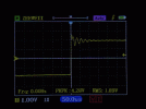
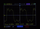
There are two approaches to dialing in the feedback compensation capacitor (the small "phase advance" cap parallel the feedback resistor)- One is to reduce amount of ringing on the square wave, to make it look much more like an ideal square wave, which visually is trading off ringing duration/amplitude for rise/fall edge rate and rounding of the edges. This is a quick and dirty approach, but can give good results.
Transformer ringing response versus feedback compensation capacitor value:

The ultimate way to adjust the compensation capacitor is to observe the measurable bandwidth above 20kHz. This bode plot is from an arbitrary 6AQ5 push pull amp I built. The blue waveform is open loop, once negative feedback is applied the improvement is remarkable at the low end, and remains constant versus any amount of feedback compensation capacitance. The difference is at the high end. The orange waveform shows a dramatic rising response and resonant peak from output transformer resonant oscillation at around 60kHz. This will vary in frequency and amplitude per transformer design. By applying more and more feedback compensation capacitance, one can find the right amount that creates a flat response all the way out to the resonant frequency.




