• The move to the new server is done. There are some software and database maintenance updates in process. This has us passing the hat around to help out. We appreciate any donations. Seriously, even a dollar helps. The payment page may be found here - https://www.audiokarma.org/support.html

How to increase power (MCS 3245 to 3275)

Racingh11

Super Member
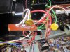
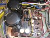
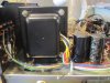
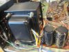
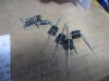
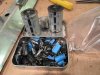
I recently went to service an MCS 3245-10 I bought. (45 watt per channel) Upon initial dim-bulb turn on, it was idling fully lit. After disconnecting things, I found that the power transformer was shorted and pulling 110W by itself. None were available, so I bought a transformer for a 3275 (75 watt per channel). It has the correct extra windings to run the amp/preamp/tuner/lights/phono/fans. I was able to mount it by drilling 3 new holes and the wires routed very nicely. Then fitted the largest filter capacitors that will fit on the board. Along with higher amperage rectifier diodes. 3 amp stock to 6 amp. The stock 3 amp diodes were then used for the power board for added 12V fans to remove the extra heat. Resistors in the power supply were also changed to keep auxiliary circuits idling at the current they were designed for. I also recalculated the current limit control resistors in the amp output to match the increased power. Then removed the speaker protection circuit breakers and installed some auto-reset poly-switches. I still have to decide if I will have a power circuit breaker like stock or use a traditional fuse. I also designed a clipping detection board and will have a colored LED flash behind the power meters. And thinking of adding LED lights to signal if the poly-switches are active for each channel.

I will add pictures and go into more detail about the parts and reverse engineering to find new values soon.
 
Last edited:
Register to hide this ad
How different was the power amp section? If its basically identical other than the voltage supply to it, sounds like a neat way to build yourself a sleeper.
 
How different was the power amp section? If its basically identical other than the voltage supply to it, sounds like a neat way to build yourself a sleeper.
The power amp section is actually about the same design as the 3275, except is adds zener voltage regulation to the differential pair(better) and a transistor to control bias current(better) compared to diodes setting it. The output transistors are also better, being a component still in production MJ15015/15016 which are rated at 120V, 15A, 180W for each. Plenty of room in those specs for this modification. And the supporting transistors are also up to the task. Just need to remove the added heat, which is what the fans will be for.

The other mod I forgot to mention is the light bar also needs to be modified. I was able to move both brackets down and will extend it 1-1/4 inch forward to make room.
 
I will have to get another scan of the 3245, file size is too big to post here, but here is the 3275 schematic. Idle voltage will go from 42.5V on the 3245 to 46.6V from the 3275. And from what I can tell, the stock transformer is 340VA and the 3275 transformer should be about 500VA. I will take side by side pictures to illustrate the difference. At first glance the transformer looked like it wouldn't work because of the 12V output at pin H, where I needed double that. Then I noticed it was only a half wave rectifier wiring and actually is a 24V center tap winding like I need. It also has a 12V winding that the lights and fans will run from. It's like they wanted me to do this. lol The power caps were upgraded from 6800uF 50V, to 10,000uF 63V which the 3275 has and with the largest ripple current available. The rest of the unit was also recapped and differential transistors replaced with matched parts.
 

Attachments

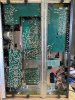
I got to work on this some more recently. It is now up and running and bench-tested. Still plan to add speaker protection and clipping lights. And finish the light bar. I had to relocate the brackets and extend it forward 1 1/4 inches. I installed a pair of PC fans that switch on at 55C. They work well. I replaced the original speaker circuit breakers with PTC poly-switches. They are mounted to the transformer on the original breaker boards. They are also functioning well. A little on the conservative side, but will see how they react with speakers tomorrow. The distortion tests just slightly higher than what I have tested on 3245s in the past, however, I did not test this one before I upgraded the parts. Larger power caps installed and all eletrolytics, along with resistor pair change in power supply board. Also the current limit resistors for the amp boards were also recalculated and changed. Everything is within spec and should hold up as if it were supposed to be this way. The distortion tests almost exactly the same whether it's at 10W, 45W, or 75W per channel, both driven at the same time.
Distortion tests as follows:
%THD
L R
20hz .060 .068
1khz .080 .090
5khz .079 .086
10khz .048 .063
20khz .038 .040

%IMD .031 .032

clipping 80W 80W
 
Last edited:
any thoughts on making those fans temperature controlled? Should be able to mount a thermistor on that heat sink to drive a control circuit that would ramp the fans up with temperature. That would keep the noise down unless the amp is hot, which is probably only going to happen when the loud knob is wound up anyway.
 
gadget, I thought he did when I read this.
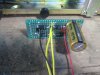
That is correct. It is temp controlled. I used simple normally open thermal switches on each side of the heat sink. They switch on at 55C and turn both fans on. I made a DC rectifier circuit to power the DC fans from the AC light bar transformer windings. It uses the original diodes I upgraded on the power board. It is in the pictures above. It's mounted to the cross-brace on the underside picture.
 
I'm supposed to be getting in an actual 3275 for service one of these days. It will be interesting to see how it compares.
 
Wow, really nice work. I love the idea of combining parts to make a better unit.
Do you have a schematic drawn up for the clipping indicator? Seems to be one of the most useful things that most home audio amps lack.
 
Wow, really nice work. I love the idea of combining parts to make a better unit.
Do you have a schematic drawn up for the clipping indicator? Seems to be one of the most useful things that most home audio amps lack.
Thanks. I have a schematic and some boards printed up. I am going to put one together and try it soon.
I think I'm going to add the speaker protection to the clipping board for the final run. Something simple like a resistor and LED in parallel with each poly-switch. When they open, it forces power through the LED. I may use a current diode instead of resistor, I'll have to see how it performs.
 
Last edited:
I played it hard today and it worked great! I had 2 sets of 8 ohm speakers hooked up. Fans and speaker protection did not come on with only one set playing. When both sets were playing the fan would come on sometimes and run for a couple minutes and cool it down. The speaker protection would come on with both sets playing hard and slightly into clipping/distortion. I think I will change out the poly-switches for the next size greater and see how it goes. I was able to hit 75W+ on the meters with both sets and 100W+ beats with one set playing. Everything ran cool, the transformer got up to around 100F after hours of playing and all other components like they were stock.
 
I also noticed a slight hum from the speakers and found the amp board connection not seated well. Plugged it on tighter and hum is gone. I may retest distortion to see if it comes down a touch to where 3245s have tested before.
Turn on and off are silent and music drops out smoothly if playing when shut down, very satisfied so far with this conversion.
 
Just retested the distortion after the driver board was plugged in tight. It improved. It's now close to what I have tested on 3245s before.

%THD L R
20hz .056 .052
1khz .054 .062
5khz .053 .052
10khz .043 .048
20khz .048 .049
%IMD .017 .017
 
Back
Top Bottom