

You are using an out of date browser. It may not display this or other websites correctly.
You should upgrade or use an alternative browser.
You should upgrade or use an alternative browser.
How to increase power (MCS 3245 to 3275)

Racingh11
Super Member
Hey, that last response was for you. Stop writing crap on this thread unless it pertains to this project.I need to fix my 3245 and cannot find any service manual or schematics, if someone can help me thanks in advance
Racingh11
Super Member
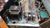
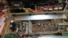
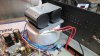
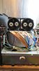
I'm doing my third power increase conversion on a 3245. A -00 white tuner version this time. Same owner as the last one I did. I had also previously went through this unit and replaced all electrolytic caps and a full service. He brought his own toroidal transformer with him, two of them actually. I was able to fit the smaller with large power caps on top. The larger transformer which is the one I want to use, will put out 40VAC x2 at 500VA. This should put it in the area of 100W 8 ohm and 150W 4 ohm. I will likely move the power board to get the 1/2 inch clearance I need. The larger trans. is 5.6 inch diameter, while the smaller 400VA trans. is 4.9 inch. There are some different voltage tap requirements with this model and may require another small transformer to handle that. The front edge of the bracket just about touches the front of the heat vent edge. It's as tall as will fit. Luckily the larger transformer is actually slightly shorter.


Last edited:
Racingh11
Super Member
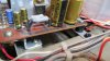
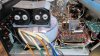
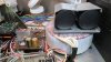
I made some brackets and moved the power board up and over. Then was able to mount the big 500VA transformer and caps. The caps are 13,000uF 100V. High ripple current and long life. I also removed the original caps. I plan to mount the auxiliary transformer in that spot if it fits. Now I need to figure how I want to wire it all together. And whether to use larger rectifier diodes on the board or mount an external rectifier bridge.

Last edited:

Racingh11
Super Member
Haha, I'm definitely looking forward to testing this one out. Should be the most powerful yet. I do have another 3275 transformer, so there will be at least one more of these conversions in the future. And now that I know what fits, I could fit pretty much any 500VA in there. But I think this one with +/-40VAC is about the limit of the heatsink with fans. I also plan to use the temperature current limit like I did on the earlier models, but with the sensors on the heatsink instead of the transformer. since it is more at risk to overheat. The fans will still be set to come on at 55C.That looks like some pretty impressive work.
Maybe that external rectifier bridge could be mounted in a nitrous bottle, totally hotrodded receiver.
I do not plan on using the transformer I had mentioned in an earlier post. I forgot it was from a MOSFET amplifier and they run 12V higher to drive them. Putting it in here with BJT outputs would have been more than the transformer, transistors, or heatsink could have handled. I think it is +/-50VAC which would be around 150W 8 ohm and 225W 4 ohm.
Last edited:
Racingh11
Super Member
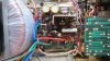
I installed the auxiliary transformer to the underside of the bracket I made to move the power board. Fits flush with the bottom. Also wired the power transformer and replaced the 2A circuit breaker with an ABC fuse holder and installed a 7 amp fuse. I wanted an 8 amp, but it's as close as I had. I will see how it does in testing, it may stay that way. The factory 3A rectifier diodes also got replaced with 6A diodes. The power supply is basically done. There are two windings left on the power transformer. 12V & 18V. The 12V will power the lights and fans. The light bar will need to be relocated about 2 inches forward. With no load attached to the high power rails, it charges the caps to +/-58.9V
Edit: 7amp fuse may be too big, I will retest with a 5 amp. The 7amp will blow if a single channel is shorted, but it's higher than necessary.
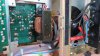
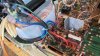
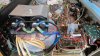
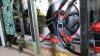
Edit: 7amp fuse may be too big, I will retest with a 5 amp. The 7amp will blow if a single channel is shorted, but it's higher than necessary.
Last edited:
Racingh11
Super Member
Calculating the resistor values for current control with PTC sensors, like the other two before this. Changing R925-928 from 470 ohm to 330. Changing R933-936 from 680 ohm to 470. And changing emitter resistors R937-940 from .39 ohm to .22. This will set the output limit to 225W 4 ohm cold, and 100W hot 60C. The 225W limit can only be reached with dynamic overhead, if at all. RMS power will not get there. The emitter resistors also need a change because they would be past their specifications. They probably would have handled it because music isn't a steady max power sine wave, but these models glue the bias transistors to the emitter resistors and would have too much temperature rise. This would lower bias tracking too much and could likely cook the transistor. Resistors can run a lot hotter than silicon junctions can. I also changed C913 from 100uF to 220uf to handle the additional voltage. The added voltage would have charged that cap quicker and raised the frequency at which the DC protection kicked in. It will now be suitable for this usage. And since this -00 model has a DC protection relay, that the -10 model does not, I will not be installing the poly-switch speaker protection on this one.
The 3245-00 schematic is a little different than the 3245-10

The 3245-00 schematic is a little different than the 3245-10
Racingh11
Super Member
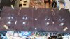
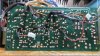
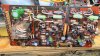
I replaced all of the audio transistors from differential input to the TO3 outputs. Also replaced the current limit and bias transistors. The gain was equal or better on all new transistors. All from On-Semi. I also replaced the emitter resistors with high quality wire wound. Replaced the current limit transistors and added connectors to the backside of the board that the temp sensors will pug in to. And also glued the temp sensors and temp switches to the heatsink. R945 still needs to be changed from 1.8k 1W to 3.3k 2W.
Last edited:
Racingh11
Super Member
Got it on the test bench today. It reaches clipping of 150W 8 ohm, and 225 4 ohm. Almost too much! Even with the emitter resistor change, they got too hot and cooked a bias transistor. I wasn't expecting this to put out so much power. I relocated the bias transistors to the heatsink along with the current limit temp sensors and cooling fan switches. I replaced the damaged components and was able to play it on some 8 ohm tower speakers. Plenty of power for sure. It tests a high of .055% THD at 100W 8 ohm, and .06% at 125W 8 ohm. .013% IMD
I also mounted the rectifier board and fans. Still have the light bar to relocate.
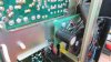
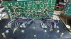

I also mounted the rectifier board and fans. Still have the light bar to relocate.
Last edited:

William Paul
New Member
It's never TOO MUCH!!! Lol!! This thing will sound amazing.
Racingh11
Super Member
It may not be too much, but it is the limit of what will fit physically, electrically, and thermally. It would be possible to go further with more heat sink and output transistors, and some extra gain in the circuit wouldn't hurt. Or maybe just use a different amp design, like one of mine...
Racingh11
Super Member
I'm hoping to have time to finish up the mods today and play it more. Any ideas for what to use the extra 18V winding for? Maybe a pump for a liquid cooling system. lolIt's never TOO MUCH!!! Lol!! This thing will sound amazing.
Racingh11
Super Member
Got all that done today and ran it hard on 2 sets of 8 ohm towers. Heatsink only heats up to 140F behind the transistor and the fans turn on. Temperature drops quickly to 115F. It will stay around 135F if played at the limit, but generally it runs 115F or less. The fans also hang over the gap between the driver board and the heatsink. The parts on the driver board drop from an already cool 110F to below 100F. The transformer only got to 80F after an hour of high volume. Very impressive!
Racingh11
Super Member
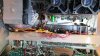
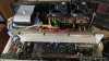
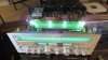
I relocated the left light bracket forward and the screw spacing fit the rectifier board i installed below. I was able to share screws. I also cut a notch for the wires to pass beneath and sliced a piece of rubber vacuum hose as a grommet. The other side was extended 1 1/4 inch forward using steel brake line cut to length. The light reflector near the tuning pulley was bent and folded in.

Last edited:
William Paul
New Member
Looks amazing.

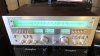
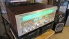
That is a very well planned and executed upgrade, quite an impressive boost in output power. Getting it to 150WPC puts it in the upper echelon of vintage receivers, I'd say. It's an exceptional looking receiver, too. I only recently (~2 years or so) took much notice of MCS gear. Have been quite surprised at how good a lot of it is both on specs and build quality after following some threads here, and in picking up an MCS 3285 and 3246 last year (both surprisingly cheap).
The NEC sourced models are all far better than one would expect from a private label brand done for a mainline department store. Reading this thread and a few others that have popped up, I may well look at getting one of these older receivers sometime this year. I have to say that I find the 3245 particularly appealing.
The NEC sourced models are all far better than one would expect from a private label brand done for a mainline department store. Reading this thread and a few others that have popped up, I may well look at getting one of these older receivers sometime this year. I have to say that I find the 3245 particularly appealing.
Racingh11
Super Member
Thank you. Glad to hear from another MCS fan.That is a very well planned and executed upgrade, quite an impressive boost in output power. Getting it to 150WPC puts it in the upper echelon of vintage receivers, I'd say. It's an exceptional looking receiver, too. I only recently (~2 years or so) took much notice of MCS gear. Have been quite surprised at how good a lot of it is both on specs and build quality after following some threads here, and in picking up an MCS 3285 and 3246 last year (both surprisingly cheap).
The NEC sourced models are all far better than one would expect from a private label brand done for a mainline department store. Reading this thread and a few others that have popped up, I may well look at getting one of these older receivers sometime this year. I have to say that I find the 3245 particularly appealing.