• The move to the new server is done. There are some software and database maintenance updates in process. This has us passing the hat around to help out. We appreciate any donations. Seriously, even a dollar helps. The payment page may be found here - https://www.audiokarma.org/support.html

How to increase power (MCS 3245 to 3275)

Well, I thought this was going to be a one time build, but I'm on my second conversion for a customer. He really liked how it turned out. This one started out with a few more problems. Both receivers were worked on before I got them. This one has all output, driver, bias transistors blown. So it got all new parts there. Will probably get the remaining audio transistors in the amp section. Will see how it compares. This time the original transformer works, so there may be a 3235 to 3245 conversion coming soon!

Update: link to the 3235 to 3245 project https://audiokarma.org/forums/index.php?threads/how-to-increase-power-mcs-3235-to-3245.984446/
 
Last edited:
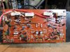
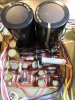
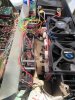
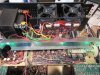
IMG_0125.JPG IMG_0127.JPG Here are some pics of the newest one. The blue film resistors on the amp board are the resistors I installed to recalibrate the current limit. The original 3245-00 sets it to 8 ohm at max power and I believe that was the intent. The later 3245-10 (this model) sets it so the output power is about 45W current-limited with a 4 ohm load, or equal to an 8 ohm rated load. The 3245-00 current-limit chokes 4 ohm loads down to 28W !! I had these setup a little different and plan to change the resistors again to get the ratio correct. The original 330 ohm resistors will now get changed to 220 ohm. This will set the 4 ohm limit to 75W, the same as the 8 ohm rating. Impedance in between those two values will tap the remaining power that the transformer is rated to put out. The 3245 is rated for 45W 8 ohm and transformer at 55W per channel, and 3275 is rated for 75W 8 ohm per channel and the transformer is rated for 87.5W. It would push about 115W RMS into 4 ohms if it wasn't current limited, but would eventually overheat the transformer if ran that high. From what I can tell, the current-limiting is there to protect the transformer from over-heating. But real music is different than a steady sine wave and the actual RMS power would not be over 87.5W the transformer is rated for as long as it was kept out of clipping. So who knows, maybe I'll try it without current-limit and see what happens. All 3 of the receivers I mentioned have transformers sized for just under 8 ohm speakers for max RMS power. The other components can handle more, and the circuit breakers were there to protect the speakers.
All audio transistors were replaced with modern parts. The current limit and muting transistors were left alone.

The power board got 5 holes relocated. The two large power caps went from 6,800uF 50V to 10,000uF 63V. Another cap from 47uF 50V to 47uF 63V. Two resistors changed from 270 ohm 2W to 330 ohm 2W. Rectifier diodes from 3A to 6A.
 
Last edited:
I think I found my answer for current limit. And I'll take an idea from the MCS 3125 for that. Adding a thermister across those resistors with the correct calculations and I should be able to allow full transformer power when cold and reduce down to rated power when hot. That will allow for increased 4 ohm performance and increased headroom across the board, and without compromising the transformer. The 3125 also adds an average power limiter to the mix, so it allows 4 ohm full power beats of 185W when cool with an average power of 125W limit, then 125 4 ohm beats and average when hot. The limit for instantaneous beats with thermal tracking is set more like a compressor circuit, not fully clipping, then the 125W averaging circuit will full clip what is above it once the cap is charged. I'm going for full 4 ohm power when cool on this one, not just the beats like the 3125.
 
Last edited:
I did some calculations and it looks like I can use the original 330 ohm resistors and add a 330 ohm 90C PTC thermister and I should get the correct 4 ohm power level at about 120W.

Another setup is to use the 330/330 pair, but change the 680 ohm current resistors to 820. When cool, this would not limit 4 or 8 ohm, and limit 2 ohm to 75W. Then at full hot, it would not limit 8 ohm, but limits 4 ohm to 75W like The ratio MCS used. And 2 ohm to 37W. Although I don't plan to drive any 2 ohm load. This may not even become active in real use, but it's nice to know it's protected and set the way I want it.

This would give 4 ohm stable performance when cool and factory style limit when hot.

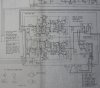
Here is the 3245-10 amp schematic. The resistors I am referring to are R929,R930,R935,R936. The stock ratio of the 680 to 330 ohm determines the voltage when the current limit transistor turns on and dumps voltage from the drivers. The voltage on the resistors is relayed from the output emitter resistors and is translated to a current measurement there. That would be the peak current and needs to be converted to find RMS current.
IMG_5810.JPG
 
Last edited:
The animal is unleashed!! I ran out of the 820 ohm resistors I need, so I ran it with the 680s pulled and turned the current limit off completely. I had already modified it some with a resistor replacement of 270 ohm in place of the 330s. I tested output with that setup and it was about 80W 8 ohm and 60W into 4 ohm. After the limit was removed, it went to 87W 8 ohm and 130 WATTS RMS into 4 ohm with both channels driven. And at .07% THD. It actually had a bit more in the tank, but the circuit breaker blows. And for the circuit breaker, I used one of the 2.5A speaker breakers and installed it in place of the 2A power breaker. It blows when power gets 120W+ fairly quick and longer at about 100W. It should work out fine with real music and speakers. That is coming soon. I also have to increase the poly-switches for the speakers, these don't stay on above 75W. I bypassed them for the test. The 8 ohm distortion also went down to .045 from .062% THD.

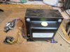
I also took the cover off of the transformer to mount the thermistors. There is not room in between windings, so I will reduce the sensing temp to 60C and mount to the outside of the windings on the copper shield inside of the cover.
 
Last edited:
Played it for 5 hours straight at high volume today. Current limit still removed. The transformer core got up to around 110F. It was in a cool room to start, but likely won't get hot enough to reduce power once I get the thermistors installed. This thing really pounded with two sets of 8 ohm speakers running. One set are MCS 8330 3-way with 12" woofers. They would have been sold in the same years as this receiver. The other pair is a set of 3-way towers with 10" heavy duty woofers. I only popped the power circuit breaker once when I was well into clipping for a bit. Really impressed with what it's doing, I'm keeping one and selling the other.
 
I just noticed something interesting. The original 3245-00 with the white tuner lens also runs lower power supply voltages of +/- 38.5 compared the the 3245-10 black tuner versions +/- 42.5V.
That calculates out to a max of 45W 8 ohm and 70W 4 ohms. But it is 4 ohm current limited to 28W as I mentioned above. The 3245-10 calculates to 55W 8 ohm and 85W 4 ohm, but current limited to 45W.
Funny thing is; the 3233 and 3235 don't have current limiting, just 3 amp protection fuses. So that means they put out more power in 4 ohms than the 3245-00 and as much as the 3245-10. Except that is will likely blow the fuses if driven too hard.
These don't have the heat-sink to cool the extra heat either, it's just in my project that current limiting is protecting the transformer. It has fans that keep the transistors below factory temperatures. I misstated that in an earlier post confusing the two setups.
So technically these receivers are 4 ohm stable, but limited to equal or lesser power. That is one thing that sets these types of receivers apart from the big boys. These two 3245s are all grown up now. :)
 
Last edited:
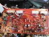
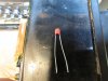
My new resistors and PTC thermistors arrived. I hooked it all up and bench tested it. I drove it at 120W and then blew on the thermistors with my hot air soldering iron. I could watch the sine wave start clipping and lower the power to a set point. When I then dial back the volume to fit in that power range without clipping, the power was down to 75W per channel in 4 ohm, just like I wanted it. Once it was verified to work, I took the cover off of the transformer and was able to push the sensors about 1/2 inch under the copper shielding strap as shown in the picture. The wires are protected with heat shrink tubing and glued in place. The picture of the board shows the new location for the resistor change. (blue resistors changed from 680 to 820 ohm) And the thermistors(range is 330 ohm 25C, to 2.2k ohm at 60C) are connected to the inner pointing leads of those resistors. They were wire wrapped to the leads and soldered and then excess leads cut off.
IMG_0138.JPG IMG_0134.JPG IMG_0139.JPG
 
Last edited:
Very cool project and amazing results!
Thanks. It has been fun. It's actually a bit of a childhood dream, in that this was the model receiver I grew up with. When I was 12 I traded my SuperScope R350 + $50 for the MCS 3245-10. I had the cover off of that one several times looking at things I wanted to improve. I really wanted to put bigger power caps in because that was something I knew about, but was afraid I would wreck something and there goes my awesome stereo. I left it alone and played 4 and 8 ohm speakers hard all the time and never did any damage. Well, now I know why... 45W limit. If only I knew to remove those resistors. haha. I also remember getting a book from the school library on hifi stereo equipment and the MCS 3275 was in there. I was disappointed to find out I didn't have the top model (wasn't aware of the 3125 at that time). But I already had a good 10 band Audio Control Octave equalizer and didn't have any interest in getting a receiver with an EQ built in and all those lights on it. I later got into cars and sold that original receiver. But 20 years later, I've now restored and owned many of them. So now it has come full circle and I got the receiver I wanted. :)
 
Thanks. It has been fun. It's actually a bit of a childhood dream, in that this was the model receiver I grew up with. When I was 12 I traded my SuperScope R350 + $50 for the MCS 3245-10. I had the cover off of that one several times looking at things I wanted to improve. I really wanted to put bigger power caps in because that was something I knew about, but was afraid I would wreck something and there goes my awesome stereo. I left it alone and played 4 and 8 ohm speakers hard all the time and never did any damage. Well, now I know why... 45W limit. If only I knew to remove those resistors. haha. I also remember getting a book from the school library on hifi stereo equipment and the MCS 3275 was in there. I was disappointed to find out I didn't have the top model (wasn't aware of the 3125 at that time). But I already had a good 10 band Audio Control Octave equalizer and didn't have any interest in getting a receiver with an EQ built in and all those lights on it. I later got into cars and sold that original receiver. But 20 years later, I've now restored and owned many of them. So now it has come full circle and I got the receiver I wanted. :)
Very cool story! I wish I had the know how to do projects like that. Recapping and replacing resistors / etc. is one thing but re-engineering is definitely out of the question here, haha. Glad that you are enjoying it!
 
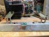
The light bar brackets moved in and extended. I used steel brake line tubing and longer screws. And had to drill two new holes in the chassis.
IMG_0147.JPG
 
Last edited:
I bench tested the 2nd 3245 today. This one got all new transistors in the amp. All modern On Semi audio transistors. Distortion improved further.

75W 8 ohm load %THD
L R
1khz .019 .015
5khz .026 .022
10khz .028 .024
20khz .022 .026

120W 4 ohm load %THD
L R
1khz .034 .028
5khz .035 .037
10khz .036 .030
20khz .033 .031
 
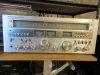
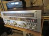
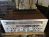
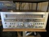
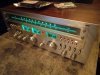
Here's some more pics. This is the second unit. I have put green bulbs in the white faced versions before and look real good, but not liking them on the black face. I switched back to clear bulbs and will post a picture of that soon.
IMG_0152.JPG IMG_0149.JPG IMG_0148.JPG
 
Last edited:
3245-75.jpg

I just got the unit home. I swapped out the clear bulbs for Green LEDs. I really like them. The pic does not do it justice. They look blue in the pic but they are def emerald green. The LEDs are way brighter than the incandescent, but they do have a flicker. The flicker is not recognized thru the faced plate tho.

VERY happy with it. Sounds AMAZING!
 
This is so tempting for the next one....
Would put it at 140 watt per channel 8 ohm and 210 watt per channel 4 ohm. And it fits. I already dropped in a big block, now it's time to boost it! lol
It will require different caps, transistors, etc; beyond the last upgrade, but should be fun.

IMG_0202.JPG
 
Back
Top Bottom