• The move to the new server is done. There are some software and database maintenance updates in process. This has us passing the hat around to help out. We appreciate any donations. Seriously, even a dollar helps. The payment page may be found here - https://www.audiokarma.org/support.html

IG04080 Possible Replacement

Yamaha5000

Never settle for 2nd best

Attachments

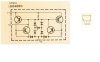
  • B6-IG04080-schematic.JPG
    B6-IG04080-schematic.JPG
    56.1 KB · Views: 29
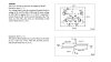
  • How-IG04080-works.JPG
    How-IG04080-works.JPG
    58.9 KB · Views: 31
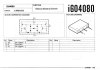
  • IC-databook-IG040800-page-109.jpg
    IC-databook-IG040800-page-109.jpg
    75.9 KB · Views: 30
  • IG04080-detail-triac-bleu.JPG
    IG04080-detail-triac-bleu.JPG
    46.1 KB · Views: 29
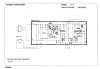
  • IG040800-application-circuit-B6.jpg
    IG040800-application-circuit-B6.jpg
    62.6 KB · Views: 30
  • Schematic 3.png
    Schematic 3.png
    149.2 KB · Views: 28
  • Simulation 2.png
    Simulation 2.png
    49.8 KB · Views: 29
Register to hide this ad
One of the Yamaha X-power supply equipped -- parts units.
 
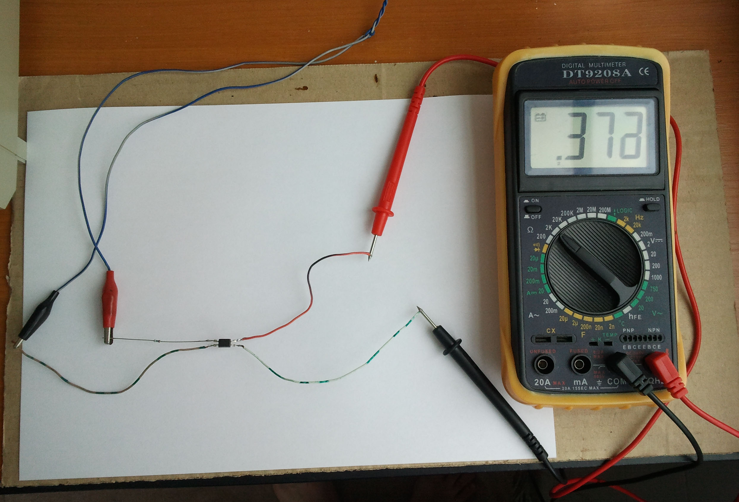
1) Connect the cold end of the 12k resistor to pins T1 and G on the IG04080. Connect the T2 pin to GND on the bench supply. With a voltmeter from T1/G to T2, it should show around 8v. Mine was 8.00v. I had expected about 9v, but 8v is better, and it is what it is. Mine is 1.31v

2) Reverse the connection of T1/G and T2. Connect the 12k resistor to T2 and ground T1/G. Again it should read 8v across the IG04080. Mine was 7.99V. This is amazingly close matching by the way. Mine is 0.65v

3) Connect the cold end of the 12k resistor to the T1 pin alone. Leave the G pin open circuit. Connect T2 to GND. Measure the voltage across T1 to T2. I expected it to be around 2.1v. Mine was around 1.3v. Mine is 0.63v

4) Reverse the connection of T1 and T2 leaving G open again. The result should be essentially the same as step 3 above. Mine is 0.67v
 
Step 1

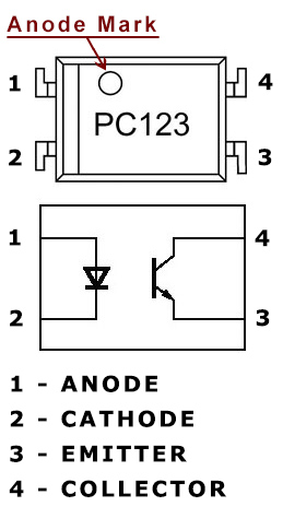
Using the diagram in the right identify the pins; first the anode and cathode of the LED ( in this case pins 1 and 2 ), and then using an ohmmeter set on the ‘X1 Ohm’ domain, measure between pins 1 and 2, and you should get one reading measuring one way and no reading the opposite way (just like you check a diode). If you get a value either way or no value at all, then certainly there is a problem with the LED, and you should find another optocoupler.

Step 2

If the LED is good then we should check the phototransistor, you could measure it with the ohmmeter just like the LED between pins 3 and 4 ( the emitter and collector ), and you should get a high resistance value both ways if the phototransistor is good. If you’ll get no reading at all, is probably because most phototransistors have such high resistance between emitter and collector that the ohmmeter can’t measure; if this is the case you could connect two ohmmeters in series thus increasing the measuring domain; …although i think most don’t have two meters so i recommend the ’empirical’ method, presuming you have a variable DC regulated power supply.

“Empirical” method

Connect the ohmmeter ( X1K Ohm or X10K Ohm ) between emitter and collector ( 3 and 4 ) like this: red probe to collector and black probe to emitter. Now connect a resistor of a few hundred ohms ( ~300 ohms ) in series with the LED anode, after this turn on the power supply and start increasing the voltage from 0 to 2…3 volts, and you should be able to see on the ohmmeter how the output resistance decreases as the input voltage increases and viceversa.
 
BC847, BC857, 1N4148W, BZX84C7V5. Models from Nexperia and Vishay.
R1: 1k...10k, in this case 3k.
R2, R3: 10k...100k, in this case 100k.
R11: 1k, but it's just for current limiting in the sim. Ignore it.

Schematics and simulaton:


sbs_sim.png (48.4 kB, 1149x516 - viewed 5 times.)
 
Why don't you say who give (or send) you the five first files ? Or what are your sources ?
Patrice

Everyone knows that you are the Moses and Avionic is the Jesus of Yamaha Audio. Are you in need of confirmation from me?

Maybe you guys could focus in providing some input on the design ideas for a replacement?
 
Hello

I don't need confirmation from you , but just saying that the documents in question were given by clinic-audio would be right and the true
 
Great contributor to finding a solution:

There original question whether a discrete solution can be used to replace the IG04080 has been answered with: Yes. (because the Yamaha part already is a discrete solution).

Can it be replaced with a 2N4991/MBS4991? IMO: No. (the "G" pin functionality is completely different).

The schematic/simulation I've provided does exactly what the Yamaha data sheet describes.

I attach the KiCAD design files (V6.0) plus the Spice models if you'd like to play with them yourself.
 
Back
Top Bottom