

You are using an out of date browser. It may not display this or other websites correctly.
You should upgrade or use an alternative browser.
You should upgrade or use an alternative browser.
IMF Transmission Line Stuffing?
- Thread starter Nickyrboy
- Start date
I built the original Bailey design more than 30 years ago following the recommendation by Jastak in the Audio Amateur (1973, 1:3).
Is this the design your built?
http://p10hifi.net/TLS/classics/Bailey-WW-TL-map.pdf
I think this is the design shown in the Bailey paper in Wireless World.

JimPA
Distinguished Member
Letters to the Editor.
http://diyaudioprojects.com/Technic...er-Enclosure-Design-Letters-to-the-Editor.pdf
http://diyaudioprojects.com/Technic...er-Enclosure-Design-Letters-to-the-Editor.pdf

keilau
AK Member
1972 Bailey TL cabinet design
I did not build this one, which was the original 1965 Bailey design. I opted for his 1972 version.
Transmission-line Loudspeaker Enclosure - zelfbouwaudio
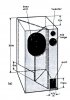
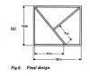
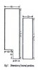
Bailey argued that the later version is easier to build and resulted in a stronger cabinet due self bracing. My TL is no long working due to driver deterioration and the wook veneer is peeling off, but the basic structure is still intact. I will show some picture later. For now, just a few drawings from the Bailey paper:
As a low income graduate student, I could not afford the British drives that Bailey recommended either. I went with the Phillips AD-10100 10" woofer following the recommendation by Jastak in the Audio Amateur (1973, 1:3). Does it work as well as the KEF B139? To be honest, no! The AD-10100 has a Fs at 32 Hz and a Vas at 111 liters, not quite up to the standard of the KEF. As usual, nothing sounds better than a DIY speaker. It is not completely subjective, the home built has lower and tighter bass than the Larger Advant by comparison.
Anybody remembers Magee Radio in Kansas City? They were the "Parts Express" in those days for speaker builders. They carried a wide range of loudspeaker brands at very good price, including the Audax, Seas, Peerless and later the Focal. The Phillips brand raw drive had since disappeared from the market.
Is this the design your built?
http://p10hifi.net/TLS/classics/Bailey-WW-TL-map.pdf
I think this is the design shown in the Bailey paper in Wireless World.
I did not build this one, which was the original 1965 Bailey design. I opted for his 1972 version.
Transmission-line Loudspeaker Enclosure - zelfbouwaudio
Bailey argued that the later version is easier to build and resulted in a stronger cabinet due self bracing. My TL is no long working due to driver deterioration and the wook veneer is peeling off, but the basic structure is still intact. I will show some picture later. For now, just a few drawings from the Bailey paper:
As a low income graduate student, I could not afford the British drives that Bailey recommended either. I went with the Phillips AD-10100 10" woofer following the recommendation by Jastak in the Audio Amateur (1973, 1:3). Does it work as well as the KEF B139? To be honest, no! The AD-10100 has a Fs at 32 Hz and a Vas at 111 liters, not quite up to the standard of the KEF. As usual, nothing sounds better than a DIY speaker. It is not completely subjective, the home built has lower and tighter bass than the Larger Advant by comparison.
Anybody remembers Magee Radio in Kansas City? They were the "Parts Express" in those days for speaker builders. They carried a wide range of loudspeaker brands at very good price, including the Audax, Seas, Peerless and later the Focal. The Phillips brand raw drive had since disappeared from the market.
Last edited:
OK, either one can be discussed in general terms.
Once these designs were built and stuffed with long fiber wool and the resonant frequencies of the enclosure measured it was determined that the frequencies were lower than predicted by the usual quarter wave equations
f = c / (4 x L)
The lowering of the frequency was calculated by Bradbury assuming that the air and fibers coupled and both moved. The added mass of the moving fibers dropped the resonant frequency of the TL and hence the speed of sound. If the speed of sound is reduced by the moving fibers then the wavelength also becomes shorter allowing the standing wave to me more like a half wavelength producing the phase inversion. Bradbury's method matched the TL behavior of the Bailey design (probably based on the one I posted not this second simple version)
Have I summed up the Bradbury theory for how these TLs work approximately correctly?
Once these designs were built and stuffed with long fiber wool and the resonant frequencies of the enclosure measured it was determined that the frequencies were lower than predicted by the usual quarter wave equations
f = c / (4 x L)
The lowering of the frequency was calculated by Bradbury assuming that the air and fibers coupled and both moved. The added mass of the moving fibers dropped the resonant frequency of the TL and hence the speed of sound. If the speed of sound is reduced by the moving fibers then the wavelength also becomes shorter allowing the standing wave to me more like a half wavelength producing the phase inversion. Bradbury's method matched the TL behavior of the Bailey design (probably based on the one I posted not this second simple version)
Have I summed up the Bradbury theory for how these TLs work approximately correctly?


c-atle-79bay
Super Member
Always wondered how you did that popcorn thing.

c-atle-79bay
Super Member
So any thoughts from the experts (said without sarcasm, cause I'm not)on the Chapman version of the transmission line that he dubs a "Compression Line" ?
If we look at the Bailey TL design I referenced in post #42 it is alot like the Fried designs described in post #13. Building one of these geometries and stuffing it with long fiber wool will result in fundamental tunings that are below the predictions made using the classic 1D wave equation.
f_tuning < c / (4 x L)
The lower than predicted frequencies are probably what started Bailey and Bradbury investigating the fiber properties in the TL. If you look at the last attachment/appendix to Bradbury's paper you will see the 1D wave equation with an added term to account for the frequency dependent viscous coupling of the air to the moving fibers. The fibers couple at low frequencies and the added mass moving with the air lowers the effective speed of sound, I have seen claims of over a factor of two in some designs. At higher frequencies the coupling is not so strong and eventually is not present at all when the frequency gets high enough.
The fundamental equation of motion shown in the Bradbury paper is the classic 1D wave equation, put your finger over the coupling term and it will match what is presented in most acoustics textbooks for a straight empty tube. The partial differential equation can be solved by separation of variables and boundary conditions used to resolve the resulting constants. This is exactly what Bradbury did, I have described the boundary conditions in a previous post in this thread.
Therefore, the difference between the predicted and the measured tuning frequencies, which are significantly lower, of the TL was attributed to the wool fiber motion slowing the speed of sound. That is the single concept that dominated TL design from the late 1960's forward. I worked with this concept for many years looking for correlation. I rederived (many times) and programmed all the equations in an old PC using Visual Basic. I believe I reproduced many of the curves in the original Bradbury paper but that was over 15 years ago and my notes are probably buried in some three ring binder on a shelf in my home office.
The 1D wave equation for a straight pipe can also be derived from the 1D wave equation for a horn. The 1D wave equation for a horn contains an extra term to account for the expanding geometry, again looking in an acoustics textbook will show the derivation of the horn wave equation typically for an exponential expansion. In fact, if instead of an expanding horn profile the geometry is tapered there will still be an extra term in the 1D wave equation. This extra term impacts the frequencies of the standing waves, for a horn that is expanding the fundamental frequency will be greater than c / (4 x L) while for a tapered geometry the fundamental frequency will be less than c / (4 x L). If you look in the document referenced below you will see examples of this in Table 1 and Attachment C. There is no fiber stuffing in these results, they are only numerical solutions to the 1D wave equation as a function of the geometry changing linearly from the closed to the open end.
http://www.quarter-wave.com/TLs/Alignment_Tables.pdf
After Bailey's and Bradbury's papers became available people started designing TLs using the moving fiber theory with mixed results, most of these designs were tapered as described for example in post #13 for the Fried TLs. If the taper was close to the one used by Bailey then the results correlated reasonsbly between predictions and measured. If the taper was significantly different then the correlation suffered. The variability in results was often attributed to not using the correct fiber material or packing density. It was claimed that wool, fiber-glass, and polyester fibers behave very differently with long fiber wool being the optimum choice. Designing TLs was somewhat of a mystical process.
The reason the results did not correlate was the exclusion of the term related to taper in the wave equation. Bradbury missed this so his whole theory of moving fibers was really a huge fudge factor to correct for this ommision. Once you include the geometry term in the 1D wave equation the fiber motion is not required to correlate predictions against test data for any TL geometry and stuffing material. Different fibers will yield different results but this is minor compared to the impact of changing the taper geometry. Geometry is critical and the fiber is a tweak. If you look at the measured versus predicted curves I plotted above you will see that for a straight TL the results correlate very well, this should have been the perfect geometry for clearly showing that the fiber motion was key to a TL's acoustic behavior. I have used raw long fiber wool and Dacron polyester in the same straight TL and the differences were subtle, there was no magic associated with the long wool fibers.
The design of TLs has matured in the past 15 years. I know of four or five separate independently developed TL design software programs that produce designs that when built and measured match the predictions. None of these codes use the moving fiber theory, they all assign a viscous damping term for stationary fibers and a slight tweak to the speed of sound to account for a partial shift between adiabatic and isothermal compression and expansion. These codes are accurate becasue they include the capability for accounting for tapered or expanding geometry in the 1D wave equation.
In conclusion, Bradbury missed the geometry term in the 1D wave equation which would have explained the frequency shifts associated with a tapered TL. The moving fiber theory turns out to be an attempt to correct for this missing term to match the test data. TL designs based on the moving fiber theory have been hit or miss depending on the rate of taper used compared to the rate of taper in the original Bailey test data.
The last design to consider is the simplified Bailey TL that you built. The taper is not so severe as the Fried and original Bailey TL. Assuming this is close to a staight pipe and the fundamental tuning is below the value calculated using c / (4 x L) the logical conclusion following Bradbury's method would again be that the wool fibers were moving. I don't believe that this is the case, I think the geometry again drives the design and for this TL it is the restriction of the area at the open end. This is more of a mass loaded TL (an ML TL) where a port is used to lower the fundamental frequency of the quarter wavelength standing wave.
All of this speculation could have been avoided if good scientific methods were used in the original measurements. When looking for the impact of one variable on a system make two measurements, one with and one without, to determine the impact. Again this is what I did in the plots I posted earlier in the thread.
All of the equations and test data I used to account for both the TL geometry and the influence of the fiber are presented on my site under the TL theory link. Íf you do the wave equation math it is an obvious result in 20/20 hindsight. I was sucked into moving fibers for years. I can only lead an old horse to water, I can't make him drink.
Any feedback/comments from other observers of the discussion.
f_tuning < c / (4 x L)
The lower than predicted frequencies are probably what started Bailey and Bradbury investigating the fiber properties in the TL. If you look at the last attachment/appendix to Bradbury's paper you will see the 1D wave equation with an added term to account for the frequency dependent viscous coupling of the air to the moving fibers. The fibers couple at low frequencies and the added mass moving with the air lowers the effective speed of sound, I have seen claims of over a factor of two in some designs. At higher frequencies the coupling is not so strong and eventually is not present at all when the frequency gets high enough.
The fundamental equation of motion shown in the Bradbury paper is the classic 1D wave equation, put your finger over the coupling term and it will match what is presented in most acoustics textbooks for a straight empty tube. The partial differential equation can be solved by separation of variables and boundary conditions used to resolve the resulting constants. This is exactly what Bradbury did, I have described the boundary conditions in a previous post in this thread.
Therefore, the difference between the predicted and the measured tuning frequencies, which are significantly lower, of the TL was attributed to the wool fiber motion slowing the speed of sound. That is the single concept that dominated TL design from the late 1960's forward. I worked with this concept for many years looking for correlation. I rederived (many times) and programmed all the equations in an old PC using Visual Basic. I believe I reproduced many of the curves in the original Bradbury paper but that was over 15 years ago and my notes are probably buried in some three ring binder on a shelf in my home office.
The 1D wave equation for a straight pipe can also be derived from the 1D wave equation for a horn. The 1D wave equation for a horn contains an extra term to account for the expanding geometry, again looking in an acoustics textbook will show the derivation of the horn wave equation typically for an exponential expansion. In fact, if instead of an expanding horn profile the geometry is tapered there will still be an extra term in the 1D wave equation. This extra term impacts the frequencies of the standing waves, for a horn that is expanding the fundamental frequency will be greater than c / (4 x L) while for a tapered geometry the fundamental frequency will be less than c / (4 x L). If you look in the document referenced below you will see examples of this in Table 1 and Attachment C. There is no fiber stuffing in these results, they are only numerical solutions to the 1D wave equation as a function of the geometry changing linearly from the closed to the open end.
http://www.quarter-wave.com/TLs/Alignment_Tables.pdf
After Bailey's and Bradbury's papers became available people started designing TLs using the moving fiber theory with mixed results, most of these designs were tapered as described for example in post #13 for the Fried TLs. If the taper was close to the one used by Bailey then the results correlated reasonsbly between predictions and measured. If the taper was significantly different then the correlation suffered. The variability in results was often attributed to not using the correct fiber material or packing density. It was claimed that wool, fiber-glass, and polyester fibers behave very differently with long fiber wool being the optimum choice. Designing TLs was somewhat of a mystical process.
The reason the results did not correlate was the exclusion of the term related to taper in the wave equation. Bradbury missed this so his whole theory of moving fibers was really a huge fudge factor to correct for this ommision. Once you include the geometry term in the 1D wave equation the fiber motion is not required to correlate predictions against test data for any TL geometry and stuffing material. Different fibers will yield different results but this is minor compared to the impact of changing the taper geometry. Geometry is critical and the fiber is a tweak. If you look at the measured versus predicted curves I plotted above you will see that for a straight TL the results correlate very well, this should have been the perfect geometry for clearly showing that the fiber motion was key to a TL's acoustic behavior. I have used raw long fiber wool and Dacron polyester in the same straight TL and the differences were subtle, there was no magic associated with the long wool fibers.
The design of TLs has matured in the past 15 years. I know of four or five separate independently developed TL design software programs that produce designs that when built and measured match the predictions. None of these codes use the moving fiber theory, they all assign a viscous damping term for stationary fibers and a slight tweak to the speed of sound to account for a partial shift between adiabatic and isothermal compression and expansion. These codes are accurate becasue they include the capability for accounting for tapered or expanding geometry in the 1D wave equation.
In conclusion, Bradbury missed the geometry term in the 1D wave equation which would have explained the frequency shifts associated with a tapered TL. The moving fiber theory turns out to be an attempt to correct for this missing term to match the test data. TL designs based on the moving fiber theory have been hit or miss depending on the rate of taper used compared to the rate of taper in the original Bailey test data.
The last design to consider is the simplified Bailey TL that you built. The taper is not so severe as the Fried and original Bailey TL. Assuming this is close to a staight pipe and the fundamental tuning is below the value calculated using c / (4 x L) the logical conclusion following Bradbury's method would again be that the wool fibers were moving. I don't believe that this is the case, I think the geometry again drives the design and for this TL it is the restriction of the area at the open end. This is more of a mass loaded TL (an ML TL) where a port is used to lower the fundamental frequency of the quarter wavelength standing wave.
All of this speculation could have been avoided if good scientific methods were used in the original measurements. When looking for the impact of one variable on a system make two measurements, one with and one without, to determine the impact. Again this is what I did in the plots I posted earlier in the thread.
All of the equations and test data I used to account for both the TL geometry and the influence of the fiber are presented on my site under the TL theory link. Íf you do the wave equation math it is an obvious result in 20/20 hindsight. I was sucked into moving fibers for years. I can only lead an old horse to water, I can't make him drink.
Any feedback/comments from other observers of the discussion.
keilau
AK Member
The fiber in a TL does not move.
No, you explained the TL theory exactly opposite to what Bradbury said in his paper. It helps if you will get a copy of the paper and read it directly. The acoustic wave is a pressure wave. So there is no net motion of the air per sec. I don't know where you got this idea of "the air and fibers coupled and both moved". (Different from blowing wind, a wave is NOT a moving mass of air. It only oscillates.) The sound velocity refers to the propagation velocity of the pressure wave which is NOT a single constant in a transmission line speaker. It varies with frequency. These are all basic college physics concepts.
Shortly after Bailey published his 1965 paper, a reader, E.A. Harman, in a letter to Editors, proposed a simplistic adiabatic theory to explain the slowing of the air velocity. He was immediately shot down by Bailey. JimPA posted a link to the letter collections yesterday. You can look it up.
I will just quote Bradbury direct from his paper and hope that it will correct your misconception of how a transmission line works:
I think that you should get the paper and read the rest of it. It is a copyrighted material and cost $25 from the Audio Engineering Socity. Bradbury went on to describe how the drag coefficient is derived. Bradbury mentioned the word "motion" in his paper, which is refered to the wave motion of the air. The drag coefficient is a function of the characterisitic wave motion time, making the slowing and attenuation of the sound non-linear with respect to the sound frequency. In both the Bailey and Bradbury paper, the sound intensity at the line terminus is unattenuated at around 30 Hz and 180 degrees out of phase.
You should not call a design a "transmission line" without this type of characteristics at the line terminus. The is the secret formula to get non ringing bass like a infinite baffer loading and the low frequency extension like a bass reflex box at the same time. You may be able to get one of the two using Martin King program, but not both at the same time.
To get a real transmission line, you must have a line filled with long fiber wool or light weight open cell foam. The success criteria is to get full sound intensity at 180 out of phase at the woofer resonant frequency Fs at the line terminus with no ringing in the resultant bass.
OK, either one can be discussed in general terms.
Once these designs were built and stuffed with long fiber wool and the resonant frequencies of the enclosure measured it was determined that the frequencies were lower than predicted by the usual quarter wave equations
f = c / (4 x L)
The lowering of the frequency was calculated by Bradbury assuming that the air and fibers coupled and both moved. The added mass of the moving fibers dropped the resonant frequency of the TL and hence the speed of sound. If the speed of sound is reduced by the moving fibers then the wavelength also becomes shorter allowing the standing wave to me more like a half wavelength producing the phase inversion. Bradbury's method matched the TL behavior of the Bailey design (probably based on the one I posted not this second simple version)
Have I summed up the Bradbury theory for how these TLs work approximately correctly?
No, you explained the TL theory exactly opposite to what Bradbury said in his paper. It helps if you will get a copy of the paper and read it directly. The acoustic wave is a pressure wave. So there is no net motion of the air per sec. I don't know where you got this idea of "the air and fibers coupled and both moved". (Different from blowing wind, a wave is NOT a moving mass of air. It only oscillates.) The sound velocity refers to the propagation velocity of the pressure wave which is NOT a single constant in a transmission line speaker. It varies with frequency. These are all basic college physics concepts.
Shortly after Bailey published his 1965 paper, a reader, E.A. Harman, in a letter to Editors, proposed a simplistic adiabatic theory to explain the slowing of the air velocity. He was immediately shot down by Bailey. JimPA posted a link to the letter collections yesterday. You can look it up.
I will just quote Bradbury direct from his paper and hope that it will correct your misconception of how a transmission line works:
Bradbury said:For the fibrous materials used in loudspeaker enclosures, the volume occupied by the fibrous material is very small (5% of the volume at most), and the small space occupied by the fibers plays no direct role in the behavior of the sound waves.
The main effect whcih the fibrous material has on a sound wave passing through it arises from the aerodynamic drag on the fibers due to sound waves. Now the fiber diameters are typically about 0.01 mm, which is much less than the wavelength of the sound waves. Under this circumstances and at the very low air velocity which arise from sound wave, it is possible to show that this aerodynamic drag is proportional to the velocity of the air flowing past the fibers.
I think that you should get the paper and read the rest of it. It is a copyrighted material and cost $25 from the Audio Engineering Socity. Bradbury went on to describe how the drag coefficient is derived. Bradbury mentioned the word "motion" in his paper, which is refered to the wave motion of the air. The drag coefficient is a function of the characterisitic wave motion time, making the slowing and attenuation of the sound non-linear with respect to the sound frequency. In both the Bailey and Bradbury paper, the sound intensity at the line terminus is unattenuated at around 30 Hz and 180 degrees out of phase.
You should not call a design a "transmission line" without this type of characteristics at the line terminus. The is the secret formula to get non ringing bass like a infinite baffer loading and the low frequency extension like a bass reflex box at the same time. You may be able to get one of the two using Martin King program, but not both at the same time.
To get a real transmission line, you must have a line filled with long fiber wool or light weight open cell foam. The success criteria is to get full sound intensity at 180 out of phase at the woofer resonant frequency Fs at the line terminus with no ringing in the resultant bass.
I have all the papers and letters, looked at them last night.
If you go to the equations of motion in the Bradbury paper there are two variables, Ua and Uf which are the velocity of the air and the velocity of the fibers coupled by a viscous damping term. We agree that these velocities are really small oscillations and not net rigid body motions. Bradbury depends on the fiber motion with the air to reduce the speed of sound.
If you go to the equations of motion in the Bradbury paper there are two variables, Ua and Uf which are the velocity of the air and the velocity of the fibers coupled by a viscous damping term. We agree that these velocities are really small oscillations and not net rigid body motions. Bradbury depends on the fiber motion with the air to reduce the speed of sound.
Last edited:
keilau
AK Member
The proof is in the pudding
Martin,
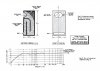
Judging from the lack of responses from other AKForumer, it is doubleful that continuing the argument on Bradbury's "aerodynamic drag" theory will be appreciated. I have a modest proposal. The picture below shows the performance of a Bailey Transmission Line using a KEP B139 woofer. It was said that the drive was customerized to increase the Vas to over 180 while keeping the Fs at 25 Hz. Would you publlish the performance of your best design from one of a similar sized woofer, either 10" round or 9"x12" oval, in a similar size cabinet. Small difference in cabinet dimension would be fine, just keep to total volume close. Then, the reader can decide which one is better for them. Bailey/Redford/TDL/IMF or Martin King.
May be some of the readers who built one from your design program will take on this challenge too and describe how their DIY would sound and whether it is better than the Bailey design. If yes, in what sense?
Let's limit the comparison to the response curve for now. Its bass extension and the decay slope tells most of the story. A very flat response down to 30 Hz and a very gradual drop-off (6dB/Octave) below that.
It would be even better if this comparison will spur some sponsor to fund some one to build 3 idential cabinets and stuff them with long fiber wool, open cell foam and Polyster fiber with the same woofer picked according to Bailey and Bud Fried selection criterion for TL woofer. It will be a really fun project. It may be a long dream, but that's how America was built.
I have all the papers and letters, looked at them last night.
If you go to the equations of motion in the Bradbury paper there are two variables, Ua and Uf which are the velocity of the air and the velocity of the fibers coupled by a viscous damping term. We agree that these velocities are really small oscillations and not net rigid body motions. Bradbury depends on the fiber motion with the air to reduce the speed of sound.
Martin,
Judging from the lack of responses from other AKForumer, it is doubleful that continuing the argument on Bradbury's "aerodynamic drag" theory will be appreciated. I have a modest proposal. The picture below shows the performance of a Bailey Transmission Line using a KEP B139 woofer. It was said that the drive was customerized to increase the Vas to over 180 while keeping the Fs at 25 Hz. Would you publlish the performance of your best design from one of a similar sized woofer, either 10" round or 9"x12" oval, in a similar size cabinet. Small difference in cabinet dimension would be fine, just keep to total volume close. Then, the reader can decide which one is better for them. Bailey/Redford/TDL/IMF or Martin King.
May be some of the readers who built one from your design program will take on this challenge too and describe how their DIY would sound and whether it is better than the Bailey design. If yes, in what sense?
Let's limit the comparison to the response curve for now. Its bass extension and the decay slope tells most of the story. A very flat response down to 30 Hz and a very gradual drop-off (6dB/Octave) below that.
It would be even better if this comparison will spur some sponsor to fund some one to build 3 idential cabinets and stuff them with long fiber wool, open cell foam and Polyster fiber with the same woofer picked according to Bailey and Bud Fried selection criterion for TL woofer. It will be a really fun project. It may be a long dream, but that's how America was built.
Last edited:
JimPA
Distinguished Member
Bailey argued that the later version is easier to build and resulted in a stronger cabinet due self bracing. My TL is no long working due to driver deterioration and the wook veneer is peeling off, but the basic structure is still intact. I will show some picture later. For now, just a few drawings from the Bailey paper:
View attachment 543377 View attachment 543378 View attachment 543379
I went with the Phillips AD-10100 10" woofer following the recommendation by Jastak in the Audio Amateur (1973, 1:3). Does it work as well as the KEF B139? To be honest, no! The AD-10100 has a Fs at 32 Hz and a Vas at 111 liters, not quite up to the standard of the KEF.
Anybody remembers Magee Radio in Kansas City? They were the "Parts Express" in those days for speaker builders. They carried a wide range of loudspeaker brands at very good price, including the Audax, Seas, Peerless and later the Focal. The Phillips brand raw drive had since disappeared from the market.
Keilau many are fond of the Kef B139 but it does have a limited Xmax of 3mm.
There are many drivers now available that are even better candidates for a Bailey T-line.
I remember McGee Radio and am not sure why they went out of business.
Precision drivers were one of their big sellers.
No, you explained the TL theory exactly opposite to what Bradbury said in his paper. It helps if you will get a copy of the paper and read it directly. The acoustic wave is a pressure wave. So there is no net motion of the air per sec. I don't know where you got this idea of "the air and fibers coupled and both moved". (Different from blowing wind, a wave is NOT a moving mass of air. It only oscillates.) The sound velocity refers to the propagation velocity of the pressure wave which is NOT a single constant in a transmission line speaker. It varies with frequency. These are all basic college physics concepts.
That paragraph is unbelievable. I am looking at Bradbury's paper right now and equation (1) couples the density, acceleration, and velocity of the fiber tangle to the velocity of the air through an aerodynamic drag parameter. Then in the paragraph just under equation 4b an expression for a reduced speed of sound as a function of the density of air and the density of fibers is shown. Appendix A includes the derivation of the 1D wave equation, without a term to account for area change as a function of length, just as I described above.
I think that you should get the paper and read the rest of it. It is a copyrighted material and cost $25 from the Audio Engineering Socity.
Clearly I have a copy of the Bradbury paper (for over 25 years), and all of the Bailey papers and letters also referenced, and I have read it, rederive the formulas, programmed it, and understand his moving fiber theory. I had thought you were simply locked into the old school TL theory that included the moving fibers, but it is clear from your statements above that you do not even understand what Bradbury was proposing with his design method.
I stand behind all of my work, the plots posted in the threads above, and the detailed description of the problems in the Bailey and Bradbury treatment of TL theory in Post #50. Everything I have done is documented on my site in what I hope is a clear and understandable format, unfortunately there is no way to avoid the math. I have not heard anything from you that would lead me to question any of my results.
Last edited:
JimPA
Distinguished Member
This is one study I found on the thermal acoustic properties of polyurethane foam.
http://www.ijser.org/researchpaper\...lyurethane-foam-modified-with-Nano-silica.pdf
http://www.ijser.org/researchpaper\...lyurethane-foam-modified-with-Nano-silica.pdf
Then, the reader can decide which one is better for them. Bailey/Redford/TDL/IMF or Martin King.
I think there is enough information in this thread for the reader to decide on a best design methodology for a TL speaker. The cabinet is going to do what is natural for its combination of driver, geometry, and fiber stuffing and not change behavior based on a label of Bailey, Bradbury, Fried, Radford, or King. The question is which method provides a reliable and robust way of designing such an enclosure where the builder can be highly confident in the resulting response. People can form their own conclusions based on the discussion and data..

ken kantor
Fowl Humor
I'd like to ask you guys a question, if I might...
Any thoughts as to the effects of SPL on the behavior of various stuffing materials?
It would seem to me that some of the propagation mechanisms proposed might well have a level dependent term in them, linear or otherwise. (Fibers can have viscosity, hysteresis, stiction, collisions, etc.) Yet, in every analysis I have seen, the effects of stuffing are treated as independent of level. TIA.
-k
Any thoughts as to the effects of SPL on the behavior of various stuffing materials?
It would seem to me that some of the propagation mechanisms proposed might well have a level dependent term in them, linear or otherwise. (Fibers can have viscosity, hysteresis, stiction, collisions, etc.) Yet, in every analysis I have seen, the effects of stuffing are treated as independent of level. TIA.
-k
keilau
AK Member
I'd like to ask you guys a question, if I might...
Any thoughts as to the effects of SPL on the behavior of various stuffing materials?
It would seem to me that some of the propagation mechanisms proposed might well have a level dependent term in them, linear or otherwise. (Fibers can have viscosity, hysteresis, stiction, collisions, etc.) Yet, in every analysis I have seen, the effects of stuffing are treated as independent of level. TIA.
-k
When Ken Kantor comes, he asks nasty questions that no one can answer. Let's face it, there is no detailed acoustic analysis of a fiber filled tube. Bradbury is the most complex that I have seen. He made many simplication and did not try to integrate the analysis with a driver due to the complexity. He pointed out the simplication in very fine details. He was able to predict the sound propagation velocity and small signal sound absorption by assuming 1-D oscillatory flow in limited amplitude. That allowed him to formulate his "aerodynamic drag" theory as purely potential flow. Therefore, there is no "viscosity, hysteresis, stiction, collisions, etc." involved. It is amazing how well his theory agrees with experimental data on fiber filled tubes.
Others assumed simple minded adiabatic or isothermal interaction or some mixture of the two between air and fiber. But no perfect coupling of air and fiber exist in nature. I will quote A.R Bailey in one of his reply to letter to editor from the 1965 paper.
Bailey-1965 said:I read Mr. Harman's letter with great interest as his theory is borne out in practice. The velocity of sound in wool is considerably slower than in free-air, and is also slower than can be accounted for by the difference between isothermal and adiabatic compression of the air. The wool mass is definitely slowing down the wave front, but as there cannot be perfect coupling between the wool and the air the effect will be some-what less than given by Mr. Harman's calculation. On the, other hand the wave will be slowed by the isothermal effects of the wool as well, so the error in assuming perfect coupling will be reduced. As Mr. Harman surmises, the velocity of sound can be slowed down very greatly in a high packing density, but unfortunately this gives rise to high back pressure on the loudspeaker cone due to the very restricted air passages. There is therefore a maximum packing density that can be used without giving a strangled effect to the sound. The maximum density varies with speaker design and cabinet design, but is far greater than the density used in the cabinet described.
We only know that 1-D wave equation coupled with driver filter model does not work well for transmission line, partially due to the nature of frequency dependent response of the TL line at the line terminus. Bradbury presented an example of limited small signal analysis that showed good promise. But after 38 years, there is no extension of Bradbury's work.
Ken, I will throw this back at you. What is your suggestion in term of testing and analysis for TL speakers? So far, the only thing that works is by trail and error.
keilau
AK Member
Keilau many are fond of the Kef B139 but it does have a limited Xmax of 3mm.
There are many drivers now available that are even better candidates for a Bailey T-line.
I am fond of the KEF B139 because it is one speaker I never had. You can call it blind faith. And of course, the B139 has many, many version. What is you #1 choice for a Bailey TL today?
I have never saw the Xmax from a KEF spec sheet. I had some spec that downloaded from a German site that stated the Xmax as 6 mm for the KEF B139 SP1044. It is quite respectable.

Some manufacturer spec the "air gap length" instead of Xmax to get a bigger number, but those are not real.
Last edited: