
• The move to the new server is done. There are some software and database maintenance updates in process. This has us passing the hat around to help out. We appreciate any donations. Seriously, even a dollar helps. The payment page may be found here - https://www.audiokarma.org/support.html

IMF Transmission Line Stuffing?

When Ken Kantor comes, he asks nasty questions that no one can answer. Let's face it, there is no detailed acoustic analysis of a fiber filled tube. Bradbury is the most complex that I have seen. He made many simplication and did not try to integrate the analysis with a driver due to the complexity. He pointed out the simplication in very fine details. He was able to predict the sound propagation velocity and small signal sound absorption by assuming 1-D oscillatory flow in limited amplitude. That allowed him to formulate his "aerodynamic drag" theory as purely potential flow. Therefore, there is no "viscosity, hysteresis, stiction, collisions, etc." involved. It is amazing how well his theory agrees with experimental data on fiber filled tubes.

Others assumed simple minded adiabatic or isothermal interaction or some mixture of the two between air and fiber. But no perfect coupling of air and fiber exist in nature. I will quote A.R Bailey in one of his reply to letter to editor from the 1965 paper.


We only know that 1-D wave equation coupled with driver filter model does not work well for transmission line, partially due to the nature of frequency dependent response of the TL line at the line terminus. Bradbury presented an example of limited small signal analysis that showed good promise. But after 38 years, there is no extension of Bradbury's work.

Ken, I will throw this back at you. What is your suggestion in term of testing and analysis for TL speakers? So far, the only thing that works is by trail and error.

Sorry. TL speakers are not my area, so I can't contribute anything very meaningful. If it were me, I would only do the obvious things: pull the design into an FEA package, start with standard materials properties, then iterate until I had an acceptable match with physical measurements. I would do my best to ignore prior art and focus on first principles. Where these were obscure, I would experiment, consult prior art, and talk to non-audio acoustics experts I know. But, as I said, Transmission Line Speakers are not really my thing. Yes, I have used TL theory to solve some very specific acoustical problems. But, these were special cases, and not at all like the kind of speakers you are discussing.

Audio technology is different than any other type of engineering I know of. In normal engineering, we start with a certain problem, and then try to invent a solution to this problem. But, in audio, most of the time, we start with an invention. Then we try to discover what it might be good for. However, just because one has a cool invention does not mean that the invention is useful or any improvement to the art. I see a little bit of this problem with transmission line speakers. Certain people invented a new way of dealing with a driver's rear radiation. Extremely clever, I admit. But, why? What does a TL do that cannot be done other ways more easily? (This is an honest question!) Of course, as just about anything in audio, TL fans will show up to exclaim that the sound of TL's is magical and different and cannot be achieved any other way. But that's just a religious belief that doesn't explain anything one way or another.

Sooo.... now that I have two of the top experts in the field available, and especially two who can talk in real scientific and engineering terms, what do you feel are the technical advantages of Transmission Line loudspeakers? (I promise I won't argue or debate, I just would like to know.)

-k
 
Sorry. TL speakers are not my area, so I can't contribute anything very meaningful. If it were me, I would only do the obvious things: pull the design into an FEA package, start with standard materials properties, then iterate until I had an acceptable match with physical measurements.

What specific FEA package are you referring to? What physical measurements will you make to assure you are achieving your objectives. For example, I want to get the bass response of the Bailey design, namely, a flat response to about 30 Hertz and a slow drop off of 6 dB/Octave below that. This is the type of bass I am looking for, nothing to do with any prior design.


Sooo.... now that I have two of the top experts in the field available, and especially two who can talk in real scientific and engineering terms, what do you feel are the technical advantages of Transmission Line loudspeakers? (I promise I won't argue or debate, I just would like to know.)

-k

There is NO technical advantage of TL speakers. The Bailey cabinets I built weight over 90 pounds each and were huge. (Big domestic disadvantage) It has only practical advantages that an average DIYer can build using commonly available parts and it does not required tuning with specific instruments. Total cost is acceptable. The sound quality is very good compared to commercial products. Like all audio gears, it is a compromise, but it works well. It is not a religious belief.

I am intriqued by the concept of a servo controlled subwoofer, but it does not seem to be feasible by an average home builder like me.

In today's HT market, most subwoofer uses tuned port design which has peaky response curve with a boomy bass. It's just not for me.

As I mentioned in my other posts, I have been using 2 modified Wharfedale aperiodic for subwoofer. They have a pair of 7" woofer each and are bi-amp. I use only the woofer section and am happy with the bass extension (to about 35 Hz) and sound too. Their appearance are much, much more acceptable to my wife. (Big domestic advantage) This aperiodic is actually fairly easy to duplicate using cabinet kits from Parts Express (300-7066). My perferred drivers at moderate cost is the Peerless CSC 850460. (I believe it was also used in one of the old NHT design.)
 
Last edited:
Ken, before answering your question I need to define what a traditional TL really is and what type of resonance is used to augment the bass SPL output from the driver. For now let’s stick with tapered or straight folded TLs seen in previous posts, for example the Bailey and Fried style of designs (and my straight TL), and compare them to bass reflex enclosure designs.

A bass reflex speaker is a second order system that mates a resonant driver to a resonant cabinet where the air in the port acts as the mass and the air in the box acts as the spring. These two resonant systems are put together and produce a second order system that hopefully produces a flat SPL above the tuning frequency, has a knee that is fairly sudden, and then quickly transitions to a 24 dB/octave roll off below the tuning frequency.

An empty TL is also a second order system that mates a resonant driver with a resonant cabinet but in this case the column of air acts as a distributed mass and spring system. Above the tuning frequency there are a series of peaks and nulls due to higher harmonics of the fundamental standing wave. There is probably a sharp peak at the tuning frequency and a 24 dB/octave roll off below the tuning frequency. Most modern TL designs are designed empty to get the tuning worked out and then stuffing is added to tame the standing wave resonances.

The differences between a bass reflex system and a TL system below 100 Hz, around the fundamental tuning frequency, are subtle. There is no huge advantage for either and both can be mistuned to provide anemic bass or boomy one note bass. I think the subtle difference is the addition of stuffing in the TL, this makes the transition from the pass band to the eventual 24 dB/octave roll off a more gradual change over a wide frequency range. This more gradual transition tends to produce a dryer bass sound and attenuates the low frequency driver deflection over a wider range of frequencies. Compared to an infinite baffle driver deflection plot, a bass reflex design will have a sharp null at the tuning frequency while a TL will have a wider depression of the displacement curve. On the down side a TL enclosure will tend to be larger than the equivalent bass reflex enclosure. Designing the TL requires a computer program as opposed to a simple look up alignment table for bass reflex.

But in audio, subtle differences are often proclaimed as huge ear opening events with recordings revealing sounds or instruments never heard before in previous listenings. For me TLs are a more interesting design to undertake with the addition or removal of stuffing providing infinite adjustment/tuning opportunities. I am not a TL zealot (only have one functioning in my house at the moment with many more OB/dipole designs) but I do find the enclosure to be a fascinating problem to work on.
 
Last edited:
I'd like to ask you guys a question, if I might...

Any thoughts as to the effects of SPL on the behavior of various stuffing materials?

It would seem to me that some of the propagation mechanisms proposed might well have a level dependent term in them, linear or otherwise. (Fibers can have viscosity, hysteresis, stiction, collisions, etc.) Yet, in every analysis I have seen, the effects of stuffing are treated as independent of level. TIA.

-k

I correlated my fiber damping model from a series of measurements of Dacron and long fiber wool at three different stuffing densities in a straight TL. I would consider it a small signal model, it is an engineering approximation on a macroscopic level without any microscopic level of analytical expressions simulating air flow past fibers. The driver was operating in a small signal mode so I expect the derived fiber damping correlation was also in a small signal mode, Increased power or the driver is assume to be handled in a linear manner.

I am sure that at some level of input signal the response starts to go non-linear and my fiber damping correlation starts to break down. This happens in all Thiele/Small models of speakers; the ports start to chuff, the driver exceeds Xmax, the horn's air compression at the throat becomes nonlinear and distortion results. It is audible in all speakers at some extreme volume level.

All I can tell you is that at even high volume levels in my listenimg room with my type of music I have not heard a degradation in performance that I would attributee to the fiber damping behaving in some manner I did not intend. I am a DIYer and not a commercial designer so I probably do not require the extremes of operation a speaker manufacturer must deal with. The wear and tear on my personal speakers is more in line with the condition of a car driven to church every Sunday by a little old lady.

That was the long answer, the short answer is I have no clue.
 
Sooo.... now that I have two of the top experts in the field available, and especially two who can talk in real scientific and engineering terms, what do you feel are the technical advantages of Transmission Line loudspeakers? (I promise I won't argue or debate, I just would like to know.)

-k
Ken, I like to know too. The first thing is the limit of Bradbury's "aerodynamic drag" theory on transmission line speakers. Since his formulation is based on potential flow analysis, it is possible that it will break down at high SPL.

What is the most relevant coupling mechanism between fiber and acoustic wave in different enclosures? We only know that pure adiabatic or isothermal coupling is physically impossible. Then, what is the best approximate model?

Is Bailey claims true when using the proper stuffing in the transmission line, namely?
  1. The woofer bass loading is similar to that of an infinite baffer.
  2. The TL tube acts as a phase inverter. The back wave comes out at the line terminus at 180 degrees out of phase with the front wave at 80% or more SPL which enhances the bass response.
  3. Only long fiber wool with a length of 5 inches or longer, corresponding to a fiber diameter of 0.028 mm behaves like that
  4. Bud Fried claimed later that he can use open cell foam to achieve the same effect.

I am not an audio person. My expertise is in the field of aerodynamics and thermodynamics. I will offer myself for conversation with your experts if they are interested.
 
B139small.GIF
What is you #1 choice for a Bailey TL today?

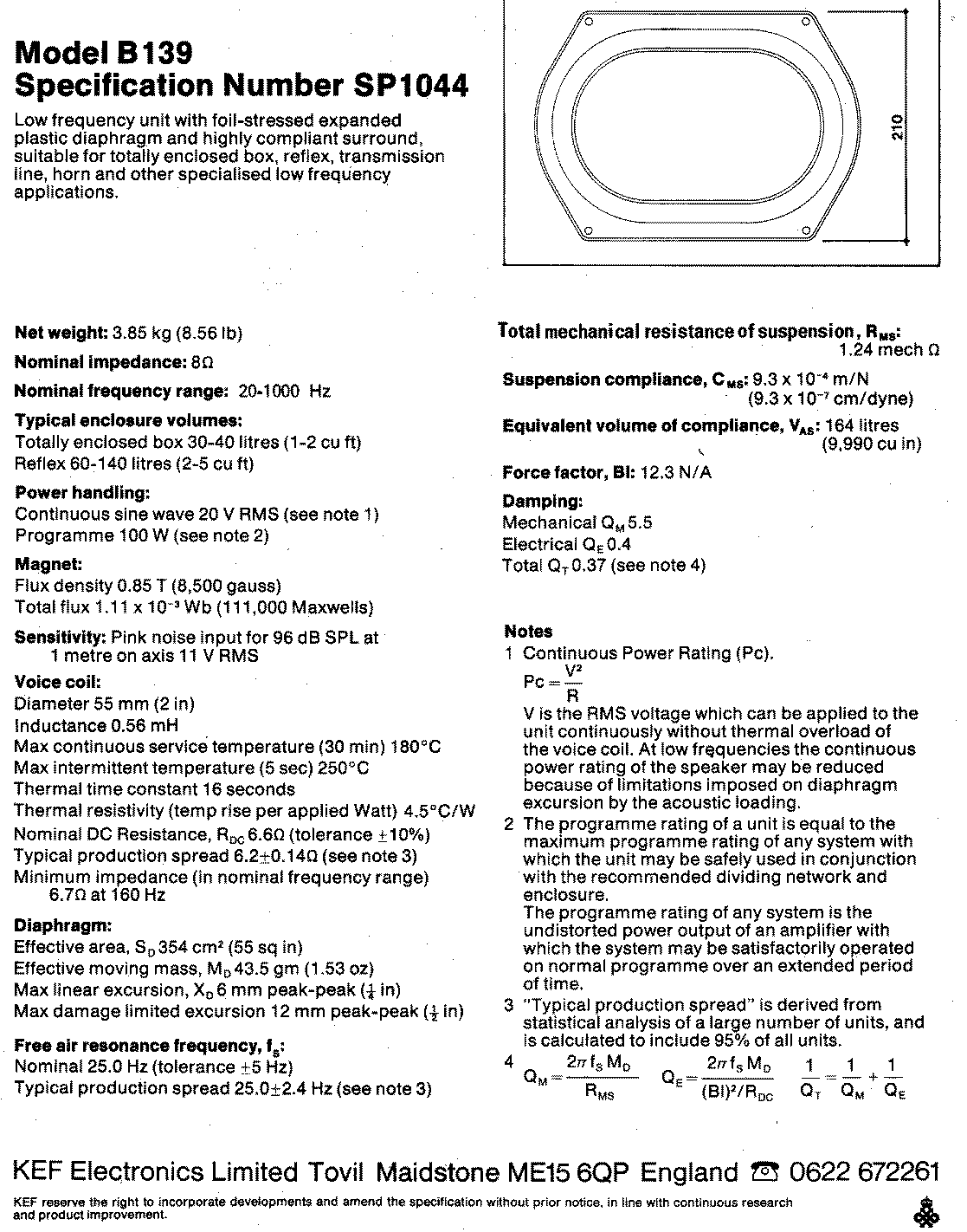
I have never saw the Xmax from a KEF spec sheet. I had some spec that downloaded from a German site that stated the Xmax as 6 mm for the KEF B139 SP1044. It is quite respectable.

Some manufacturer spec the "air gap length" instead of Xmax to get a bigger number, but those are not real.

For the cost the Eclispe 1038 now being made by Misco.

https://www.madisoundspeakerstore.com/approx-10-woofers/eclipse-w1038r-10-poly-cone-woofer-8-ohm/

http://p10hifi.net/TLS/drivers/images/B139B_newer.gif

The peak to peak is kind of misleading on the B139 since the Xmax is derived from deducting the voice coil gap height from the voice coil length and dividing by 2.
 
Sorry. TL speakers are not my area, so I can't contribute anything very meaningful. If it were me, I would only do the obvious things: pull the design into an FEA package, start with standard materials properties, then iterate until I h

Sooo.... now that I have two of the top experts in the field available, and especially two who can talk in real scientific and engineering terms, what do you feel are the technical advantages of Transmission Line loudspeakers? (I promise I won't argue or debate, I just would like to know.)

-k

Ken I have done listening comparisons of the Fried designs I have built.
The best example is the model C aperiodic design compared to the C3L T-line design.
Using the same exact drivers and crossover in both designs that I built the T-line design revealed more nuances and details that I never heard in the aperiodic design.
Freeing the cone of any reflections inside the enclosure is the reason for this.
Also having sound coming from the line terminus vent opening unloading into the room creates a second sound source. I hate to refer to this sound as point source.
Fried always claimed the T-lines are plane source and not a spherical sound source.
 
What specific FEA package are you referring to? What physical measurements will you make to assure you are achieving your objectives. For example, I want to get the bass response of the Bailey design, namely, a flat response to about 30 Hertz and a slow drop off of 6 dB/Octave below that. This is the type of bass I am looking for, nothing to do with any prior design.


There is NO technical advantage of TL speakers. The Bailey cabinets I built weight over 90 pounds each and were huge. (Big domestic disadvantage) It has only practical advantages that an average DIYer can build using commonly available parts and it does not required tuning with specific instruments. Total cost is acceptable. The sound quality is very good compared to commercial products. Like all audio gears, it is a compromise, but it works well. It is not a religious belief.

I am intriqued by the concept of a servo controlled subwoofer, but it does not seem to be feasible by an average home builder like me.

In today's HT market, most subwoofer uses tuned port design which has peaky response curve with a boomy bass. It's just not for me.

As I mentioned in my other posts, I have been using 2 modified Wharfedale aperiodic for subwoofer. They have a pair of 7" woofer each and are bi-amp. I use only the woofer section and am happy with the bass extension (to about 35 Hz) and sound too. Their appearance are much, much more acceptable to my wife. (Big domestic advantage) This aperiodic is actually fairly easy to duplicate using cabinet kits from Parts Express (300-7066). My perferred drivers at moderate cost is the Peerless CSC 850460. (I believe it was also used in one of the old NHT design.)

OK, I understand. Thanks!

Since I haven't thought that much about it, I didn't have any particular "FEA" or test procedure in mind. For the FEA, there are so many available!

http://www.dmoz.org/Science/Technology/Software_for_Engineering/Finite_Element_Analysis/

In the past, I have used ANSYS for complex acoustical modelling. I have also used Martin's worksheets successfully to design some small, non-traditional "TL's."

In terms of measurements, I would have to try some things to see what made the most sense. Probably, I would rely on nearfield mics, weighted by radiating area, but I might try to double check this using some ground plane or beanpole measurements, just to confirm I was on the right track.

-k
 
Ken, before answering your question I need to define what a traditional TL really is and what type of resonance is used to augment the bass SPL output from the driver. For now let’s stick with tapered or straight folded TLs seen in previous posts, for example the Bailey and Fried style of designs (and my straight TL), and compare them to bass reflex enclosure designs.

A bass reflex speaker is a second order system that mates a resonant driver to a resonant cabinet where the air in the port acts as the mass and the air in the box acts as the spring. These two resonant systems are put together and produce a second order system that hopefully produces a flat SPL above the tuning frequency, has a knee that is fairly sudden, and then quickly transitions to a 24 dB/octave roll off below the tuning frequency.

An empty TL is also a second order system that mates a resonant driver with a resonant cabinet but in this case the column of air acts as a distributed mass and spring system. Above the tuning frequency there are a series of peaks and nulls due to higher harmonics of the fundamental standing wave. There is probably a sharp peak at the tuning frequency and a 24 dB/octave roll off below the tuning frequency. Most modern TL designs are designed empty to get the tuning worked out and then stuffing is added to tame the standing wave resonances.

The differences between a bass reflex system and a TL system below 100 Hz, around the fundamental tuning frequency, are subtle. There is no huge advantage for either and both can be mistuned to provide anemic bass or boomy one note bass. I think the subtle difference is the addition of stuffing in the TL, this makes the transition from the pass band to the eventual 24 dB/octave roll off a more gradual change over a wide frequency range. This more gradual transition tends to produce a dryer bass sound and attenuates the low frequency driver deflection over a wider range of frequencies. Compared to an infinite baffle driver deflection plot, a bass reflex design will have a sharp null at the tuning frequency while a TL will have a wider depression of the displacement curve. On the down side a TL enclosure will tend to be larger than the equivalent bass reflex enclosure. Designing the TL requires a computer program as opposed to a simple look up alignment table for bass reflex.

But in audio, subtle differences are often proclaimed as huge ear opening events with recordings revealing sounds or instruments never heard before in previous listenings. For me TLs are a more interesting design to undertake with the addition or removal of stuffing providing infinite adjustment/tuning opportunities. I am not a TL zealot (only have one functioning in my house at the moment with many more OB/dipole designs) but I do find the enclosure to be a fascinating problem to work on.

Thanks much. I completely agree with your take.

One comment, though: As far as I know, a TL is a 4th-Order system, just like a non-assisted vented system. A sealed box is a 2nd-Order system. Each degree of order represents a pole-zero pair, and 6dB/oct. rolloff.

-k
 
I correlated my fiber damping model from a series of measurements of Dacron and long fiber wool at three different stuffing densities in a straight TL. I would consider it a small signal model, it is an engineering approximation on a macroscopic level without any microscopic level of analytical expressions simulating air flow past fibers. The driver was operating in a small signal mode so I expect the derived fiber damping correlation was also in a small signal mode, Increased power or the driver is assume to be handled in a linear manner.

I am sure that at some level of input signal the response starts to go non-linear and my fiber damping correlation starts to break down. This happens in all Thiele/Small models of speakers; the ports start to chuff, the driver exceeds Xmax, the horn's air compression at the throat becomes nonlinear and distortion results. It is audible in all speakers at some extreme volume level.

All I can tell you is that at even high volume levels in my listenimg room with my type of music I have not heard a degradation in performance that I would attributee to the fiber damping behaving in some manner I did not intend. I am a DIYer and not a commercial designer so I probably do not require the extremes of operation a speaker manufacturer must deal with. The wear and tear on my personal speakers is more in line with the condition of a car driven to church every Sunday by a little old lady.

That was the long answer, the short answer is I have no clue.

One of the reasons I was thinking about this is that it might represent a bona fide technical advantage of TL over Vented: lower air velocities at higher SPL might yield lower distortion and noise. I'm just not sure at what kind of levels this becomes significant at, or how size factors in.

-k
 
Thanks much. I completely agree with your take.

One comment, though: As far as I know, a TL is a 4th-Order system, just like a non-assisted vented system. A sealed box is a 2nd-Order system. Each degree of order represents a pole-zero pair, and 6dB/oct. rolloff.

-k

Ken,

You are absolutely correct, sealed is 2nd order and BR/TL are 4th order. My mistake, typing faster than thinking.

I have also used ANSYS to model TLs, the problem I had was the inability to put a frequency dependent acoustic impedance at the open end. I could only produce undamped frequencies and mode shapes with out the correct open end boundary condition.

Martin
 
Ken,

I have also used ANSYS to model TLs, the problem I had was the inability to put a frequency dependent acoustic impedance at the open end. I could only produce undamped frequencies and mode shapes with out the correct open end boundary condition.

Martin

Not an issue in the stuff I was doing, but I could certainly see that. I know that there are a slew of new, audio-optimized FEA and BEA applications available now, though I have only used a couple of the very driver-specific ones. I hope they have addressed some of the limitations of ANSYS.

-k
 
Ken I have done listening comparisons of the Fried designs I have built.
The best example is the model C aperiodic design compared to the C3L T-line design.
Using the same exact drivers and crossover in both designs that I built the T-line design revealed more nuances and details that I never heard in the aperiodic design.
Freeing the cone of any reflections inside the enclosure is the reason for this.
Also having sound coming from the line terminus vent opening unloading into the room creates a second sound source. I hate to refer to this sound as point source.
Fried always claimed the T-lines are plane source and not a spherical sound source.

Thanks, but as I mentioned, I am only considering the objective technical characteristics of the TL, for the moment. A plane source? Why ever would that be?!

-k
 
ken kantor;8165008 Why ever would that be?! -k[/QUOTE said:
The line makes the dispersion pattern a plane source.
This claim was made in Fried's many writings.
 
Ken, I like to know too. The first thing is the limit of Bradbury's "aerodynamic drag" theory on transmission line speakers. Since his formulation is based on potential flow analysis, it is possible that it will break down at high SPL.

What is the most relevant coupling mechanism between fiber and acoustic wave in different enclosures? We only know that pure adiabatic or isothermal coupling is physically impossible. Then, what is the best approximate model?

Is Bailey claims true when using the proper stuffing in the transmission line, namely?
  1. The woofer bass loading is similar to that of an infinite baffer.
  2. The TL tube acts as a phase inverter. The back wave comes out at the line terminus at 180 degrees out of phase with the front wave at 80% or more SPL which enhances the bass response.
  3. Only long fiber wool with a length of 5 inches or longer, corresponding to a fiber diameter of 0.028 mm behaves like that
  4. Bud Fried claimed later that he can use open cell foam to achieve the same effect.

I am not an audio person. My expertise is in the field of aerodynamics and thermodynamics. I will offer myself for conversation with your experts if they are interested.

I think that aerodynamic drag is a pretty good first-order approximation of what is actually happening, along with a slight effective path-length increase due to tortuosity. Of course, there is some thermodynamic component, evidenced by the imaginary component of the enclosure's acoustical impedance, but it is secondary.

-k
 
Ken how could the anti resonant line terminus frequencies be spherical in nature when emerging from a rectangular vent?
 
Perry S.Marshall has some good insight on T-line designs.

http://perry.pdfs.s3.amazonaws.com/transmission_line_derivation_perry_s_marshall.pdf

Neville Roberts came up with an 1/8 wave length design.

http://rssconsultancy.co.uk/article85b.pdf

Read the bottom half of this page to see what Perry Marshall now thinks about TL design. It is different from what is contained in his older college paper.

http://www.perrymarshall.com/articles/industrial/transmission-line/

There is no such thing as an 1/8 wave length TL, every TL is quarter wavelength and the geometry can be used to push the tuning frequency up or down.
 
One of the reasons I was thinking about this is that it might represent a bona fide technical advantage of TL over Vented: lower air velocities at higher SPL might yield lower distortion and noise. I'm just not sure at what kind of levels this becomes significant at, or how size factors in.

-k

Someone I correspond with on TL designs once approached me with a severly tapered geometry (20:1 I think) where the open end was so small that he was worried about the potential for chuffing noised sometimes heard in a bass reflex design. The numbers all indicated he was in the range that you typically try and avoid for small diameter ports. But the TL did not end in a port where there is a large area discontinuity at both ends of the port, there was just the discontinuity of the TL exit. I have never bought into the relationship of port noise to some fluid flow parameter like Reynold's number but have leaned more to suspecting back and forth wave reflections created at each end of the port tube, in the case of this TL there was potential for a reflection at the open end but the backwards traveling wave needed to go all the way back through the fiber stuffing to the closed end before coming back. We discussed this and he went ahead and built the design. Even though the opening was very small he never heard the typical chuffing or noises associated with bass reflex enclosures and undersized ports. This might be an advantage of TLs over bass reflex designs for this special atypical geometry.
 
Back
Top Bottom