• Please note that Audiokarma will be offline briefly for updates early on Monday morning, September 28th.

Improving A Vintage Phono Stage For Less Than $2.00!

I guess I can't leave well enough alone.

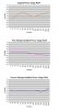
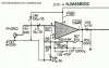
In my initial modification of the phono stage I had lowered the low-end cut off by changing C59 and R03 to 47µF and 392 ohms, respectively. Although I didn't fully appreciate it at the time, lowering R03 also increased the in-circuit gain of the op amp by about 9 dB and made the phono stage more noisy since it was now more sensitive to the ground layout/loops. I did change the location of a grounding strap, but that only partially solved the issue. So I decided to lower the gain by increasing R03 to 2K; now the gain was ~14dB lower (~5dB lower than the original stock circuit) and the noise problem was gone! Interestingly, this also improved the RIAA curve (although not likely to be audible). Another effect was that the upper end of the RIAA curve now resembles Allen Wright's proposed modified RIAA curve (to account for the cutter lathe response), see http://www.stereophile.com/content/cut-and-thrust-riaa-lp-equalization-page-2 .
 

Attachments

  • sy335 phonomod2.jpg
    sy335 phonomod2.jpg
    90.3 KB · Views: 120
  • final SY-335 phono.jpg
    final SY-335 phono.jpg
    73.7 KB · Views: 98
This is a very interesting post. Thank you for sharing you experiences with us. I am following this thread with great interest as my Pioneer SX-8 has basically the same circuit and I have been interested in updating it.
 
Okay, I found a service manual for the SY-330, which is apparently the same on the insides. Here's the complete breakdown:

C01/C02: Replace 10uf/35 (no value change)
C48/C49: Replace 47uf/16 with 100uf/25
C59/C60: Replace 4.7uf/35 with 47uf/50
C11/C12: Omit
R03/R04: Replace 1k with 2k
R05/R06: Replace 560k with 619k (Parallel two 120k resistors and series them with the 560k)
R07/R08: Replace 47k with 51.1k (I used a 33k and an 18k. Tested a bunch until I got really close to 51.1k)
R63/R64: Omit

I'm listening to the first Violent Femmes album on vinyl, pumped through this preamp right now. It's nice and quiet, and I didn't even use the DD-designated op-amp. (Digikey didn't have it, but I added a socket to the board so I can swap it in later).

I've also done the power supply mods and the main op-amp upgrade as well. I have two of these suckers. I've done all these mods to the original version, and I have a Mk. II that has been in my system for a while now, and it's completely stock. I'm looking forward to swapping in this freshly updated amp to see if I can notice any difference between them.

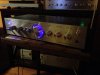
In addition to these mods, I've replaced the power LED with a blue LED, and I added three small LEDs behind the main volume knob, to illuminate the knob so I can see what the volume is set to when the lights are dimmed. It looks pretty cool!

SY-335-blue.jpg

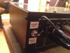
Finally, I installed a phono bypass switch. In one position the phono circuit works as normal (RIAA preamp working), and in the other position the RIAA is bypassed, and the Phono input works just like any other line input (such as AUX or Tuner)

IMG_1907.JPG

Charles.
 
Not really! The low end cut-off was lowered to minimize the effect of the capacitor on the audible range. Many designs use a cut-off closer to 1Hz!

Yep. Be aware, that time-delay effects of a frequency rolloff (phase errors), exist to a SIGNIFICANT degree, even as far away as two octaves from the rolloff point.

So, if you want the most linear (in time) response at 20 Hz, you'd want the LF rolloff of the phono stage to be 5hz or so. 10Hz is probably "good enough" for most cases.

Also, be aware, that these time delay errors are CUMULATIVE. If the phono stage rolls off, then the preamp rolls off, then the amp rolls off, then the speakers roll off, the time errors ADD! At some point, this DEFINITELY becomes audible. Hence, removing as many of these cascading errors as possible, is a good idea...

Regards,
Gordon.
 
Thank you for doing all the hard work for me!

I have the MKII of this preamp, but you forgot to mention you need to do both channels :) I also replaced the exact same op amp on the main board (I am not sure what it's for but it's on the tone control board).

The whole unit sounds a LOT better. I don't have to use the loudness control anymore, just a bit of bass boost and a tiny bit of treble on vinyl.

There's definitely a lot more bass, I can tell. And the sound is louder, except that if you turn the volume knob all the way up, there is still some hum and hiss. Nothing to worry about because it does not interfere with listening at all.

Oh, and I checked the PSU with my old Tektronix scope and I didn't see any noise at all. So the hum is probably being picked up from the transformer even though it's shielded.

Cheers!

-Tom
 
For anybody doing this stuff I strongly suggest building as precise an inverse RIAA circuit as possible. That makes it far easier to measure the response, which is darn near impossible to do well directly, and lets you see square wave response, which is instantly revealing of errors.
 
For anybody doing this stuff I strongly suggest building as precise an inverse RIAA circuit as possible. That makes it far easier to measure the response, which is darn near impossible to do well directly, and lets you see square wave response, which is instantly revealing of errors.
I'll say it. Perhaps you could explain this a little more.
Thanks!
 
A good place to start is http://www.hagtech.com/pdf/riaa.pdf Whether to do the traditional or modified network is up to you- I go with traditional.

With a good inverse network everything is so much easier at the test bench. The signal is divided down to cartridge levels and you don't have to rely on a meter or scope being accurate between ranges, which you would normally have to change as the gain changes with frequency. One quick glance at a 400 Hz (or so) square wave tells you if there are any major problems. It makes things as easy as testing a flat amp.
 
I thought I would contribute my own research on here. This will apply to any 70s preamp. I've never seen a PSU that sophisticated that doesn't even seem to be regulated.

So I ordered 12 CAD adjustable PSU board on eBay from China. I picked one that looked like it had enough capacitors :)

I got this one:

http://www.ebay.ca/itm/181927232280?_trksid=p2060353.m2749.l2649&ssPageName=STRK:MEBIDX:IT

It looked tiny in the picture, but this thing looks like it could easily deliver at least 1A at 30V! Doesn't matter, that's the smallest I could find.

Then get an around 5-7VA toroidal transformer (I got it from Digikey) you want at least 16VAC secondary. I made a small mistake and got 24V two secondaries, but powering a couple op amps will not overheat these voltage regulators.

The good thing: When the volume knob was fully up I heard a slight bit of an odd hiss (not quite white noise). It's gone. Totally silent on Aux input. The phono stage still picks up some hum though, but may be a bit better.

This is the result:

Thanks the the original poster!

Old equipment can still sound great. I paid 50CAD for this preamp and it was fully working then about 30CAD in parts to redo the phono stage and the PSU.

Thanks!

-Tom
 

Attachments

  • rebuild_PSU.jpg
    rebuild_PSU.jpg
    84.6 KB · Views: 62
Just a quick update. I shorted the phono inputs and turned the volume to max (that's more than twice the listening level). There's pretty much no hum, just some kind of weird noise (barely noticeable). So it's pretty much quiet. My Grado Blue seems to be picking up everything in the room.

Cheers,

-Tom
 
Good job Tom!

Thanks!

One final mod if you have the MKII (not sure if yours has this). I thought my turntable was mistracking (it was driving me nuts), but somehow the microphone board was acting up, probably a bad solder joint. So on the board there is R in R out and L in L out marked. Just bypass that microphone preamp. She sounds great now!

Best,

-Tom
 
For anybody doing this stuff I strongly suggest building as precise an inverse RIAA circuit as possible. That makes it far easier to measure the response, which is darn near impossible to do well directly, and lets you see square wave response, which is instantly revealing of errors.


I don't know how accurate this is but seems like a good place to start (especially if you're not good at engineering, design and fabrication)


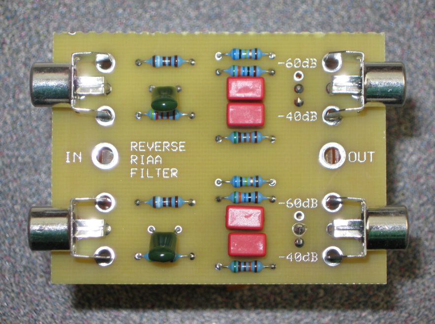
for testing & evaluation of phono preamps, plug your CD player or sig gen into this, it does 40 to 60 db (selectable) attenuation,
and filters the frequency response in exact reverse of the RIAA EQ, so flat freq input going thru the filter and then thru your phono section give flat freq output!

rRIAA-71.jpg
reverse RIAA filter kit $35 includes shipping (inside USA only)

(tubes4hifi)
no affiliation


I don't know how accurate this is but seems like a good place to start (especially if you're not good at engineering, design and fabrication)


for testing & evaluation of phono preamps, plug your CD player or sig gen into this, it does 40 to 60 db (selectable) attenuation,
and filters the frequency response in exact reverse of the RIAA EQ, so flat freq input going thru the filter and then thru your phono section give flat freq output!

rRIAA-71.jpg
reverse RIAA filter kit $35 includes shipping (inside USA only)

(tubes4hifi)
no affiliation


Neat! Thanks for sharing.
 
Cool, yes I've seen that PCB before on some site.

BTW, I was able to do it with just my computer and a $100 CAD sound card about 15 years ago and Cooledit. I had a cheapo record player going straight into an analog mixer at pretty much full gain into the sound card. Recorded into Cooledit then one of the filters was 'reverse RIAA'. I'm pretty sure it was able to do the opposite too. :D

Best,

-Tom
 
Back
Top Bottom