• The move to the new server is done. There are some software and database maintenance updates in process. This has us passing the hat around to help out. We appreciate any donations. Seriously, even a dollar helps. The payment page may be found here - https://www.audiokarma.org/support.html

Improving Fisher's Heater String Cathode Bias System

dcgillespie

Fisher SA-100 Clone
Subscriber
I have dealt with the various problems of this design approach many times on AK, either with those looking to have the power amplifier section of interconnected console pieces operate in stand alone fashion, or with those whose output tubes are (literally) burning up in such designs. An example of an in depth project that takes an amplifier designed around this concept and modifies it for maximum performance can be found here:

https://www.audiokarma.org/forums/index.php?threads/improving-the-fisher-x-101c.582379/

But dealing with the problems of this type of design in the manner discussed in that thread is often more than many AKers want to take on or feel comfortable implementing.

With renewed interest being shown in the problems of this biasing concept again, I thought it would be an opportune time to introduce a much simpler modification I devised to alleviate the problems of these designs, so that output tube life and operating temps would no longer be something you'd cringe about every time you operate the amplifier. The modification won't improve performance over the original design as was achieved in the thread above, but original performance levels will be maintained, and your tubes and transformers will breathe a huge sigh of relief just the same. But first, an understanding of just what the problem is.

The concept seems so simple: Use the output tube quiescent current to power the heaters in the small signal tubes. What a win-win deal! DC current is applied to the heaters of the small signal tubes to eliminate any possibility of hum from operating them on AC, and it doesn't require an additional power supply to do it. How cool it that? It's so simple, what could go wrong? Well, that's coming up. Before that however, a few basics.

Fisher used this scheme in numerous stand alone and console models with both 7591 and 6BQ5 class tubes. With high transconductance and similar biasing requirements, both of these tube classes -- when used in push-pull stereo designs -- have collective quiescent current requirements that are well in the ball park of that needed to light a 12AX7 heater when operated in its 12 volt configuration. By adding just a little more voltage to the power transformer's high voltage winding then, it was easy enough to apply this scheme to two, three, and even four series connected 12AX7 heaters to obtain the benefits of DC operated heaters.

The only apparent down side was warmup time: The output tubes had to warm up before they could pass any current to then allow the small signal tubes to warm up. In models that employed a 5AR4 rectifier tube, the warmup time was extended even further because this tube intentionally takes longer to warm up than typical output tubes do. And, because Fisher always operated their DC powered small signal tube heaters at less than their nominally rated voltage (typically in the 10-11 vdc range to maximize signal to noise ratio), this just added insult to injury in the warmup time department. As a boy, we'd turn on Dad's X-101ST (which included all these factors) on Friday, if we wanted to listen to records on Saturday. An exaggeration of course -- but not by much!

Ultimately, it's easy enough to get beyond the warmup time issue, but there was one other pesky little problem to deal with -- and that problem is ultimately what causes so much angst about how the output tubes operate in these models today -- and the problem is not simply higher AC line voltages, although that surely aggravates the issue.

All Fisher amplifiers operate the output stage in Class AB mode, a class characterized by high efficiency and low distortion. The down side of Class AB operation however is that as power output increases, the current drawn by the output stage increases accordingly -- and significantly. Therefore, a 6BQ5 design that might otherwise have a collective cathode current of 130-135 mA under quiescent conditions, could have a collective cathode current of 250 mA with both channels operating at full power. Oops. 12AX7 heaters won't last long in that scenario! Clearly, as the output stages draw more current, the voltage drop across the tube heaters goes up (since they are a resistive element) -- endangering the tubes, and reducing power output in the process.

To guard against this situation from getting out of hand, Fisher always strapped a high wattage resistor across the cathode heater string. This resistor serves one purpose: it prevents the cathode voltage from rising significantly as power output is increased in both channels. This safeguards the small signal tube heaters and, prevents the loss of power output from the increasing voltage drop that would otherwise occur across the heaters in this scenario without the resistor installed. But there's just one problem. The resistor effectively amounts to a shunt regulator, which is never very efficient.

Inefficiency means heat in any electronic device. In my own subject X-101D that I developed this modification on, the stock shunt regulator scheme draws an incredible 37.3 watts of power from the power supply, and then dissipates that energy in (primarily) the output tubes, and the shunt resistor as well -- 33.9 watts in the tubes, and 3.4 watts in the resistor. On a per tube basis, that means that each output tube is dissipating 8.5 watts of energy that's doing nothing but protecting the small signal tube heaters, and maintaining a few extra watts of audio power. Then of course, there's the added heat under the chassis from the resistor, and also the heat not accounted for yet that's developed in the power transformer in working to supply all this extra power. The result is that even with the unit operating from 115 vac, the well balanced output tubes are each dissipating 19.55 watts, or 103% of their Design Maximum Pd rating in the stock design. No wonder the most common complaint today about this design scheme is red platting output tubes!

The goal then is to develop a way to protect the small signal tube heaters and maintain the power output of which the unit is rated for (at least as well as the stock design did), and all without over-dissipating the output tubes, adding any under chassis heat, or cooking the power transformer in the process. The modification proposed here does just that, and is easy to implement. And, with a slight alteration to the parts used, the modification works in either 6BQ5 or 7591 based designs, regardless of how many heaters are (or are not) strung together in the output tube cathode circuit. The remedy to all these problems is the Zener Diode, which is ready made for this application --well that, and the characteristics of a 12AX7 heater. Next time.

Dave

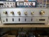
The volunteer test unit the modification was developed on:
SAM_2924.JPG
 
Register to hide this ad
CONCLUSION

So the Zener diode comes to the rescue, and does an admirable job in this application.

Taking specifically the X-101D, from purely an amplification requirement standpoint, the optimum quiescent cathode current for each output tube is 35 mA, or 140 mA for the four output tubes combined. Now on average, in the 12 volt configuration, a 12AX7 heater will draw 140 mA with 11.75 vdc applied to it. There may be some variation from one tube to the next, but I've never seen this vary more than 2 or 3 mA maximum. The X-101D has four 12AX7s strung together in the cathode circuit, so conveniently, if the modified amplifier employs one 12 volt 5 watt 5% Zener diode per tube in the cathode string, this will make up a 48 volt clamp for a 47 volt (11.75 X 4) heater circuit. Add in a current sensing resistor for adjusting the bias, and the modification is complete. On paper, the modification looks like this:

Heater String Bias Modification.jpg

Values for the bias control network and cathode bypass cap are not shown, since these would vary from one model to the next. In the X-101D, the bias control ended up being set virtually where it was when this unit left the factory. No adjustment to the bias network resistors should be required to support this modification, with plenty of adjustment range available to accommodate hot or cold biasing tubes, or anything in between.

Set the bias control initially to a low current setting (wiper towards resistor that is grounded), and then come up to the target setting. Final adjustment should be made after 15 minutes of operation, after which it will remain appropriately stable. If you overshoot the setting by even a rather small amount (say to about 1.45 vdc with the X-101D), the Zeners will come alive and start sinking current rapidly -- exactly like they are supposed to. The voltage at the bias test point will then shoot up markedly, letting you know you need to back off on the setting.

At a setting of 1.35 vdc in the X-101D, the heaters are conducting 135 mA of current, and the bias network conducts another 5 mA, for a total current flow of 140 mA. This means the tubes are now conducting 35 mA each, of which about 32.5 mA is plate current. With the reduced current draw, B+ from the power supply rises of course, to about 475 vdc in my unit -- operating from a 121 vac line with a 2A current limiter installed. Each 12AX7 heater has 11.75 vdc across it so that this voltage across 4 tubes, plus the 1.35 vdc at the bias test point, has the cathodes of the 7591 tube operating at 48.35 vdc. As can be seen then, the overall plate to cathode voltage has increased to 423 vdc (rounding, and accounting for OPT primary winding losses), but with a plate current of 32.5 mA, each tube is now dissipating just 13.75 watts at the plate -- way, way down from the 19.55 watts of the stock design.

Biased as recommended, the Zener diodes normally draw zero current -- even during normal music play, since the cathode bypass cap acts to hold the cathode voltage steady during the presentation of transient material (music). When the amplifier is driven to full power output in both channels (25 watts RMS each), the output stages draw a combined total of 250 mA from the power supply. The Zeners immediately kick in after about 150 mA of current draw and clamp the cathode voltage at about 53 vdc, producing near nominal heater voltage across the 12AX7 tubes. The amplifier now heats up in about 40 seconds, and you can actually see the 12AX7 tubes producing a normal heater glow in them.

Zeners are not perfect regulators, as heat and current will affect their avalanche point. In this application however, as an easy modification to the stock design, normally setting idle, and only called upon for short periods quite intermittently, they are an outstanding answer, producing much better regulation than the stock design, and allowing the output tubes to operate (by comparison) at very cool operating levels.

An appropriate Zener value is also shown for amplifiers employing 6BQ5 tubes. The discussion has centered around the X-101D, but the modification concept and circuit actions will be identical relative to the voltages typical with 6BQ5 amplifiers.

Matched output tube quads are still required, and should always be employed anyway. However, with the tubes now operating so much cooler, the requirement of having such an extremely tight match between them is now greatly alleviated. Also, some of the smaller amplifiers did not include a bias control, but merely included a couple dropping resistors to set the bias voltage developed across the heater string. In those instances, it is recommended to install a control, which can be added right at the point where the divider resistors connect to the four output tube grid return resistors (similar to that shown on the schematic presented). The value of the control will depend on the value of the resistors used in the divider network, but in any case, the control should be of the linear taper type.

The recommended Zener diodes are a stock item at Mouser. I also added an extra T-Strip in my unit to define the bias test point. The diodes, a T-Strip, and the current sensing resistor then are all you need to make for a major improvement to any Fisher piece employing a heater string cathode bias design.

Dave

A pic of the modification: A closeup of the Zener string that replaces the old green 450Ω resistor. The Zeners, the added T-Strip to provide a bias test point, and the 10Ω 1W resistor make up the total modification. The addition of a CL-90 current limiter are the only modifications to this otherwise stock, all original X-101D.
SAM_2927.JPG
 
Last edited:
Dave.

I really enjoy each post that you write. :). With all this valuable info, I think you have enough history to make a book where is sure I'll buy one copy.

My most admirable respect!!

Thanks for keep running the vacuum tubes alive!!!

Luis.
 
On my list of many things to get around to doing was trying to work out a method of using zener diodes to sort this exact issue in my TA-600. Considering that amp has been sidelined needing filter caps for too long now, obviously I haven't put all that much effort into it. I strongly suspect it will improve power output, at least on the 600 which has no shunt regulator arrangement.
 
:lurk:

I've got a Fisher KX-100 and X100B (nearly identical brothers), both of which have the mentioned small signal tube heater design. They use 7868 tubes.

I was planning on an EFB(tm) at some point which fixes that design compromise among other things but well, I'll have to wait and see what magic Dave has in mind this time.
 
Last edited:
Tim. I like it. It's simple, direct, and above all UNCOMPLICATED(from a schematic view) and CHEAP! From what I see, this mod should work on the 7868 based amps with no modifications of the 7591 schematic. I sure as hell am gonna try this on one of my 481A-490T setups as a mule. If it works on a stock 481A, I'm eventually gonna look at the 610 radio head (60 consolette) and a 30A amp. Maybe even my R-20 and or the R-3 chassis.
 
Thanks Dave ! Clever design. I will look at modifying my 480A/490T console. There is no high wattage resistor across the cathode string in the 480A amp ?

I blew 3 output tubes out of two matched quads trying to get this thing working ! I then cobbled together a quad of the remaining tubes that seems to work but one of those tubes are way (10 ma) off though. I also have a brand new matched quad sitting on the bench for when I get this thing modified.

My amp is stable now with bias voltage on pin 3 set to 29 volts. That voltage only varies about .5 volts either way. I have only played the amp at low to moderate volume levels so far though. Three output tubes are running at about 12 watts idle expect for the odd ball tube that is only running at 8 watts idle. AC line voltage set to 114 VAC. Plate to cathode voltage is 355 VDC. Measured plate current average 33 ma.

This has been quite an experience ! Thanks for all or you help !

Joe
 
Another outstanding bit of wizardry from Dave, this may be the first mod I do on my bone-stock, working x-101-d. Many thanks, Dave!:bigok:
 
Well, let me back up a moment based on the comments made by Gadget and H3HEE, regarding my statement that Fisher always strapped a large resistor across the heater string. With their comments that their units don't include such a resistor I went back and looked at some of the older models that used 6BQ5 class tubes, and confirmed their comments -- although not absolutely. Obviously there was a big assumption on my part, that started with my dad's X-101ST, and does in fact have a 950Ω resistor strapped across the two DC powered heaters in that model. If they did it then, and they did do it in all their 7591 tube class models, then who knew they stopped adding the shunt resistor in later 6BQ5 models only? Apparently not me! But then there is the somewhat strange case of the SA-16.

Perusing the Fisher Console site, the earliest mention I can find of this amplifier being used was in the 1960 Coronet Console (C-808). But even then, it is operated in stand alone fashion because the tuner/preamp associated with it in that console is the self powered 100-T. But a power plug is clearly provided for supporting an associated un-powered unit -- which examination of the SA-16 schematic strongly suggests was never for a tuner/pre chassis: The way B+ is provided to the power plug and the lack of any extra heater winding to support the tuner circuits all but confirms this. Therefore, this amplifier -- when powering an associated unit -- must have only been installed in a phonograph only consolette type unit. Larry -- can you confirm?????

The point of the discussion about the SA-16 however centers on the operating voltage appearing at the cathodes of the output tubes -- 19 vdc, with their control grids elevated above ground to produce the proper quiescent current. There's only one reason to do this, which is of course to support the operation of two external 12AX7 heaters, with the shorting plug replacing those heaters with an internal 125Ω 7W resistor when the amplifier is operated in stand alone fashion. What's unknown then is if whatever this little external preamplifier device is (almost surely designed for use with a ceramic cartridge) includes a shunt resistor across the heaters -- but I seriously doubt it does. With19 volts across a 125Ω cathode resistor, that equates to 152 mA of current flow. Add in one more mA drawn by the bias divider network (which uses the same values as that used in apparently later versions of the X-101ST by the way, which then don't include a shunt resistor either ) and it means that the the output tubes are flowing 153 mA of cathode current, or 38.25 mA per tube. Subtracting out for the screen current places the plate current at 34 mA. With a plate to cathode voltage of 351 vdc, it means that the Pd in each tube (if perfectly matched) is 11.9 watts -- or right at the Design Center Pd maximum rating for 6BQ5 class tubes of 12 watts. This is surely operating the tubes at typical dissipation limits of the day, made possible because the Design Center rating system is more conservative than the later Design Maximum system, taking into account both manufacturing tolerances of the tube and tolerances of the associated components used as well.

So where is all of this going? Well, a number of things seem to be mandatory facts regarding 6BQ5 units using the heater string bias system:

1. Operation at the correct AC line voltage is a must. From my experience, Fisher equipment of this era employ power transformers wound for 115 vac operation. The SA-16 is rated for operation between 105 and 120 vac -- but man-oh-man, I'd be quite leery of operation near 120 vac.

2. A tight match of the output tubes is a must. With the tubes operating so close to limits, any mismatch at all will quickly send those tubes carrying more of the load into orbit. Those with these units should seriously consider adding an IBAM or IBBM feature to their amplifiers to ensure a balanced quiescent between all four tubes.

3. For those using Fisher 6BQ5 based basic stereo amplifiers like the SA-16 in stand alone fashion (including similar Fisher units modified to operate in stand alone fashion) which employ the heater string bias arrangement, and desire improved performance, then consider converting to a more traditional bias arrangement (control grids referenced directly to ground, smaller cathode resistor, and adjusted screen grid voltage as appropriate). This move will inherently work to limit upward movement of cathode voltage due simply to the much smaller cathode resistor value this will allow. If this approach is followed, then the addition of Zener diodes will offer little performance improvement, with obviously no heaters to protect, either. The ultimate approach to take in this instance however would be to employ an EFB™ cathode regulator to provide output stage bias, which will then produce all the benefits that mode of operation has been shown to provide.

4. For those console and integrated amplifier applications where the cathode bias series heater string is to be maintained, then the addition of Zener diodes to 6BQ5 amplifiers: (1) won't allow the output tubes to operate any cooler or the unit to warm up any faster, since there isn't a shunt resistor to remove that allows the tubes to cool down, or to allow the shifting of more current to the series tube heaters. But (2) it will still provide protection against upward cathode voltage movement with increasing power output (of which there was no protection before), which will act to protect the series tube heaters, and likely increase power output as well since upward movement in cathode voltage would now be very restricted.

It is clear then that Fisher was operating their 6BQ5 designs at (basically) maximum dissipation ratings to facilitate operation of the heater string. Cathode biased designs inherently operate tubes near or at maximum dissipation ratings anyway, but with the heater string biasing arrangement, it meant that now there was much less leeway allowed in all the various tolerances involved -- tube, components, and AC line voltage. In other words, everything must be spot on for the system to work properly and with good dependability, so the points above really need to be followed closely.

Ultimately then, the 7591 is much more suited to the heater string bias arrangement due to it's increased current handling and dissipation ability. But even then, the X-101D is a perfect example of how hard the tubes still had to be operated to facilitate both the heater string, and reasonable performance when a resistor is used as the regulating element. Here then, the use of Zener diodes represents a significant advance in terms of tube life and operating temperature. With the 6BQ5, the heater string biasing arrangement makes for a convenient way to power the small signal tube heaters with DC power, but it really hamstrings these tubes from the power and performance of which they are capable of. The lack of any stabilizing resistor with this tube when the heater string scheme is used is evidence enough as to the limits the tubes are being operated at. For lower tier integrated and console duty units however, they work well enough using the heater string, but the limitations and compromises are significant. Any significant improvement to those amplifiers would require the approach outlined the the X-101C thread, to facilitate both maximum performance, and the small signal tube heaters. Simplicity is what drives this thread however, with the information provided hopefully allowing each to get the most out of their Fisher for the goals they have for the application it represents.

Dave
 
The 808 had, like you surmised the 100-T self powered Tuner/pre. The phono could either be powered off the SA-16 or the 100-T. I don't recall seeing or hearing of a Remote phono off switch on the 808. The 808 and the 1961 C-55 apparently were the only units the SA-16 was placed in, as I can find no other references to it in the FISHER Service manuals for 1959 thru 1961. The 440 series of amps,(440-A, 460-A, 480-A, 481-A and the 490A) did not have a shunt resistor as part of the original design. The amp fed either 3 or 4 12ax7 on the tuner (depending on the year and tuner #). When converted over to standalone a 5W shunt resistor (270Ω or larger IIRC) was installed to compensate for the loss of the tube heater string. The 1961 C-55 Coronet was also available with the SA-16 but with the 101-T Tuner/pre. I don't see any changes between the two years as far as hookup btwn the amp and the Tuner. The 500-S was available as an option on the C-55.

The 30A from 1958 thru 1960 was strictly a standalone in the extension speaker housing (30000 series) for the 1959/60 560 consolette extension speaker, and the 1960 C.E. III (610 &560 in one cabinet.) and as a strictly standalone mono amp. No resistor required.
 
Last edited:
Thanks Larry -- I keep assuming that the S-16 must have been used in some phono only (no tuner) application, as otherwise, why include the power take-off plug on it at all? The S-16 was not designed to support a tuner -- just a very simple preamp chassis.

Dave
 
So the zener string will work in the 440 series, just not as effective. However, the level of protection is justified to protect, or rather negate higher cathode voltage when driving the amp, correct? The schematic the same?
 
On my 480A amp I can crank the volume up very loud (3/4 volume or more ) while watching the cathode voltage on pin 3 momentarily jump up .5 volt or so and settles right back down to where I have it set at 29 VDC. It's self adjusting in other words. That's how I thought cathode bias worked ? So I'm not experiencing what Dave was talking about on his unit ? I may be confused :)
 
Good questions both --

Toxic -- You are correct in that there is no resistor to remove that was drawing heavy current like there was in the X-101D -- because the 6BQ5 tubes can't support the current flow for the tube heaters, and any more through a shunt resistor. They're already using all available current to power the heaters. But, it will prevent the rise with increasing power output. Not only that, if a heater opens in the phono preamp for example, before, the entire unit would go dead because there was no current pathway once the heater circuit opened up. With the Zeners in place, the unit will still play by drawing all output tube current (then) through the Zener string. Of course the one phono channel would still be dead as a door nail!

N3 -- A good idea to try and see what's going on, but you can't really see it that way. Music is transient by definition. The component that works to keep the cathode voltage constant under transient conditions in this type of amplifier (i.e., a Class AB amplifier) is that big bypass cap attached between the cathode terminals and ground. The class that the output stage operates in determines how much of the time the tubes conduct current. For example, in a Class A push-pull output stage, both tubes conduct current all the time throughout the entire power output range of which the amplifier is capable of. Therefore, Class A push-pull amplifiers don't need or use a cathode bypass cap -- since the tubes conduct in a mirror image fashion of each other at all times, the voltage at the cathode by definition remains constant. In a Class AB design however, at higher power output levels, one tube turns off while the other carries the load, and visa versa. The required cathode bypass cap will act to hold the cathode voltage constant (which if not present would cause a significant loss of power output), but can only do so under transient conditions. But what about steady state conditions? Imagine a powerful 32 foot pipe organ note held for maybe 10 or 15 seconds. The bypass cap will still work to eliminate any loss of power that would otherwise be lost across the cathode resistor, but cannot stop the inevitable rise in total average current flow that occurs in all Class AB designs. In the lab, the pipe organ note could be replaced with a sine wave test signal. If a milliamp meter were then connected between the power supply and amplifier, you would see it rise sharply as power output increased. Since the tubes in Class AB amplifiers do not work symmetrically then throughout a major portion of the input waveform (only at low power levels), there must be an increase in average current draw to support the increased power output available from Class AB designs over Class A designs. Specifically then, it is the increase in cathode voltage in cathode biased designs, produced by the increase in average current draw of Class AB output stages at high levels of power output, that the Zeners act to clamp. Between them and the cathode bypass cap, the cathode voltage is clamped pretty well. It's not as good as a true fixed bias design, but a darn sight better than a standard resistor based cathode bias design -- and it protects the tube heaters in the heater string as well.

I hope this helps!

Dave
 
Thanks for great wright-up Dave! With suggestions from other members I used your TA-600 IBA mod in HK TA-5000x and always wondered if those cathode string resistors (voltage divider for original bias supply) could be eliminated to reduce power waste generated by outputs. This is great solution to lower unit's temperature. Biased within limits and no red plating but it does run like a personal space heater. On the other hand, I wonder how much of effect this will have on B+ ? It has to rise, correct?
 
On the other hand, I wonder how much of effect this will have on B+ ? It has to rise, correct?

B+ wouldn't be affected. The zeners would simply "cap" how high the cathode voltage can swing under high power output conditions. I don't see why this wouldn't work on any amp using the same basic circuit design though.
 
Really nice design. I might try it out on my Fisher KX100. (It already has an IBAM, but my IBAM should/might work as long as the individual pots/parts I chose for the IBAM have enough adjustment range.)

Interestingly, Dave's diagram has an adjustment for the overall bias of the entire output tube quad which is something the stock KX-100 never had! (Ala Fisher X100B which is the major difference between the KX-100 and X100B.)
 
Last edited:
Back
Top Bottom