• The move to the new server is done. There are some software and database maintenance updates in process. This has us passing the hat around to help out. We appreciate any donations. Seriously, even a dollar helps. The payment page may be found here - https://www.audiokarma.org/support.html

Improving Fisher's Heater String Cathode Bias System

Please forgive my dumb questions.

1. Is the cathode bypass cap in Dave's diagram the original value from the unit or is it adjusted for the zener modification in any way?

2. Would there be any measurable impacts of the zeners clamping the cathode voltage on the audio output? I.e. Would that clamping appear at the plate as some change in the output waveform since the cathode voltage would no longer be floating based on the cathode current? (Maybe its an AC vs. DC thing and is a non-issue. I just don't know, so I thought I'd ask.)

3. The small signal tube warmup still depends on the output tubes starting to conduct, right? I.e. Still slower than if there were a dedicated heater supply for the small signal tubes?

4. In Dave's post 15 in the first paragraph he talks about the zeners providing an alternate current path to keep the output tubes going when a phono tube heater goes open. Not sure what he meant. I thought that in that scenario, all 4 small signal heaters would lose current and the amp would stop working out of both channels (upstream) anyway. Did I misunderstand his point?

5. Is there any advantage to running the small signal tube heaters cooler? (i.e. Starved. I know it slows warmup, but thought I'd ask as I remember reading that heater starvation was a "thing".)
 
Last edited:
How about subbing in a 250-300 ohm 10 watt cathode resistor for the preamp heaters and then power the 3 preamp tubes in series with an external 36 VDC supply. I think I have a few 28-36 VDC laptop power bricks in my junk box. This approach would remove the preamp tubes from the bias scheme altogether. Minimal work required. Just an idea.
 
How about subbing in a 250-300 ohm 10 watt cathode resistor for the preamp heaters and then power the 3 preamp tubes in series with an external 36 VDC supply. I think I have a few 28-36 VDC laptop power bricks in my junk box. This approach would remove the preamp tubes from the bias scheme altogether. Minimal work required. Just an idea.

Yep. That is one way. Dave's EFB(tm) has a more elegant solution that uses a filament transformer to do the same thing. (I've actually picked up two filament transformers because the ones he used are getting harder to find from RS.) Or you could just sub in a resistor in series with the heaters to drop a few volts across the heaters. Still I was wondering if less is more (volts) in the heater string no matter how you get there.
 
Last edited:
Hi Tim -- Answered in order:

1. Unlabeled on my schematic as I indicated since they could be different between various models. Value unaffected by the presence of the Zeners.

2. The only measurable difference would be a potentially slight increase in power output, since any upward movement in cathode voltage represents a loss of available B+ voltage to produce power output. The Zeners do a better job of regulation in the X-101D than the 450Ω resistor does, but the main benefit is their only drawing power when they need to, versus all the time by the resistor. Any increase in power output produced is not a significant factor, nor a good reason for implementing the modification. It's presented to save excessive dissipation in the tubes, and lower operating temps accordingly.

3. Correct.

4. Now doggonit, there you go making sense out of absolute rubbish! You're absolutely correct that the amp would still go dead. Before it was because of an open tube heater so all four tubes would be dead -- and the resistor would still let the output stage draw current. Now the amp still goes dead, and the Zeners still let the output stage draw current. So what's the difference? Not a dang thing!!! Thanks for keeping me honest. The development and write up of the modification was a rush job in between other projects to try and help out a few folks having related issues with the X-101C and D amplifiers, and that allowed dumb comments to creep into the write up. Thanks for catching it!

5. Operation below the nominal rated heater voltage has been shown to improve S/N ratios slightly -- but once you've reduced the voltage by 10%, there's really no further benefit to be had with any further reduction in heater voltage. Starved current operation (of which reduced heater voltage was but one element of), was an attempt to extract maximum gain from a tube, with no particular focus on or claim regarding noise that I recall.

Dave
 
Great work again Dave. I really have to figure out how that I can adapt this to a Fisher x-100-3. It's biasing schem is missing a lot compared to your X-101D
 
How hot are those zeners expected to run at full output? Any reason to think about sinking them? In Audible Illusions preamp I have power supply diodes have copper clip heat sinks on them. I'm not sure if those were original or someone added them later because those diodes do get hot. Hot enough to melt the solder!
 
No. With both amplifiers at a full boil, the output tubes are collectively drawing 250 -260 mA. Now the voltage at that point across the Zener string has risen to about 50 volts (Zeners aren't perfect regulators), or 12.5 vdc across each 12AX7 heater on average, which almost exactly equals the nominal voltage rating for the 12 volt heaters of these tubes -- point being, that of the 260 mA being drawn, now about 150 mA is flowing through the 12AX7 heaters, with 110 mA is flowing through the Zener string. With each Zener being a 12 volt, 5W device, that means that each Zener is dissipating 1.32 watts, which represents just 26% of their 5W rating. The Zeners could even handle the full current draw of the output stages at a full boil if necessary, but of course as discussed previously, that can't happen as for the Zeners to handle all output stage current draw, it means that the heater string must be open at some point, and if so, then none are lit, so no drive could be produced.

Dave
 
I'm going to implement this next time I open up my X-100-B. I drew up the attached schematic, depicted in the same orientation that the X-100-B service manual (sn 20001-29999) schematic has things shown.
First question: Do I have this right? (Terrible drawing skills notwithstanding...)

I figure I should just do my IBBA while it's open, since I have a number of really tightly matched pairs of old american 7868s, but no quad that matches better than 9% across all 4 for cathode current. I plan to use an externally adjustable implementation of the IBBA as depicted in Dave Gillespie's excellent thread here: https://audiokarma.org/forums/index...dividual-bias-adjustment-modification.601583/

So, my second question:
When implementing the IBBA mod in conjunction with the zener clamp mod discussed in THIS thread, will I eliminate C4, the 100uF capacitor, as well as the existing bias pot and associated R69, and R76?
Or just the pot and resistors?

And my last question, how does the process of setting the bias differ when IBBA and the zener modification are both implemented?
 

Attachments

  • 20200306_180300.jpg
    20200306_180300.jpg
    35.6 KB · Views: 202
Last edited:
Your drawing is just fine! For independent bias adjustment, the easiest thing to implement that would be to replace the existing 5K bias control with 4 paralleled 20K controls, with the wiper of each control serving the grid of one tube. The IBBA approach will also work, but with a supply of about 48 volts supplying it, the concept would be exactly the same, but it would have to be designed from scratch so that the range of the controls was correct. However, that approach would certainly be best, as trying to set four individual IBAM controls would likely be quite tedious to do, although certainly possible. With the IBBA and matched tubes, you're effectively only adjusting two bias controls, and then just tweaking the two balance controls for equal current flow in the tubes they serve.

In implementing any individual adjustment modification, C4 must remain, since ultimately this is still a cathode biased design. The existing pot and resistors -- depending on which way you go -- would either be removed completely for the IBBA approach, or just the 5K pot replaced with 4 new pots as described above if using the IBAM approach.

In terms of setting the bias -- and this is why I say the IBBA might be easier to use -- it is exactly the same in that you are looking to achieve 1.35 vdc across the 10Ω resistor at the bottom of the heater/zener string -- except that you also want an identical voltage drop across the individual 10Ω cathode resistors when there is 1.35 volts produced at the main test point. Cumbersome to say the least, although once set, it should hold well. The cumbersome element is what you pay for if not going the full fixed bias route as described in the X-101C thread I referenced. Again, however, this whole approach was offered as a very simple alternative to really cool the tubes down yet maintain all the original performance, without having to go the full measure as described in that thread. As you go beyond the basic modification described here to implement individual bias adjustments, things get more complicated either way you go.

Dave
 
This is a good mod for the 500-C to reduce heat, yes? I've been away (making music instead of upgrading components that plays it) and want to get back in. If I'm understanding, I replace the huge mother of a resistor (orange R143 1.2k 7W in my case) with 4 zeners in series. Thorne
 
Nice to have you back! But no -- this modification would not be applicable to any of the Fisher receivers or their upper tier integrated amplifiers. It is strictly a console only intended and lower tier product modification.

Dave
 
Thank-you Dave for sharing this very important modification for those of us with cathode biased amplifiers!
Can't wait to install this on my X-101-C.
Also thanks to Tom Bavis for pointing me in this direction with the link.
 
Thanks to Dave for this modification -- it looks like something I'd like to try on my KX-100. I ran across the thread while searching for info that might help me solve an oscillation problem. This Zener string will be on my list after sorting out the current problem. Has anyone successfully used this mod in a KX-100? If so, how? Thanks to all.
 
Thanks to Dave for this modification -- it looks like something I'd like to try on my KX-100. I ran across the thread while searching for info that might help me solve an oscillation problem. This Zener string will be on my list after sorting out the current problem. Has anyone successfully used this mod in a KX-100? If so, how? Thanks to all.

I have a KX-100 and it's factory built brother the X-100-B. I have zero doubt that it would work just fine in them but I haven't circled back to them yet for further work, however.....

I recently installed it on an X-100-A and it's working wonderfully. The X-100-A circuit is slightly different in that it uses EL-84 tubes and only has 3 tubes in the small signal heater/bias network. Other than that the zener implementation is very close to the same.

This is another gold standard design from Dave! Thanks Dave!!
 
Last edited:
On my list of many things to get around to doing was trying to work out a method of using zener diodes to sort this exact issue in my TA-600. Considering that amp has been sidelined needing filter caps for too long now, obviously I haven't put all that much effort into it. I strongly suspect it will improve power output, at least on the 600 which has no shunt regulator arrangement.

so I finally bought a couple of round tuits and a zener diode. Went with a 22v 5w part. 1N5358 for those playing along at home. I mounted it right along side the cathode cap, hanging off the two phono tube sockets. Space and access are not your friends in a TA-600 and that was the least difficult spot to add it.

Stock voltage at idle: 20.0
stock voltage at full pwr: 26.6
full power, both driven 9.5 wpc

Zener voltage at idle: 20.0
zener voltage at full pwr: 22.05
full power, both driven 11 wpc

Thats full power before the tops start to flatten out. Crossover distortion in stock form sets in about 8.5 watts. With the zener in place I get no visible crossover distortion at all. I didn't measure the THD but visibly it looks a lot better. Its not enough extra power to make a difference but hey, free power and less distortion along with easier life on the phono tubes for under 50 cents. I'll call it a win.
 
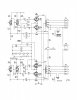
I don’t know whether I should revive this thread or start a new one, but I am hoping to modify my KX-100 with Dave Gillespie’s Zener diode string, as well as a couple of other things picked up on this forum. Before I lift a finger, I want to make sure I have these things correct. Attached is a scan of the relevant part of the X-100-B schematic with the following changes made:

-Added Dave’s diode string and 10 Ohm 1w resistor

-Added Dave’s 100 Ohm 1/4w screen stability resistors

-Changed C25, C27, C26, and C28 to 0.1 uF

-Changed R57, R59, R58 and R60 to 220k Ohms

For clarity on the schematic I show the connection to R72, which is part of the power supply section otherwise not shown. I have removed from the schematic the bias pot and changed the bias resistor values to reflect the original values on the KX-100 (an aside: has anyone ever seen an actual KX-100 schematic?).

Questions:

-Does this modified schematic look correct? Have I missed anything?

-Does Dave’s Zener string mod require a bias pot? If so, what value? And would it require changing the value of the stock KX-100 bias resistors (R69 and R76)?

-What is the recommended value for the Zener diodes?

-Somewhere I read that R71 (560 Ohms) should be a higher value. If so, what value?

-Is 0.1 uF an appropriate value for the coupling caps, and is 220k OK for those resistors? Or should I revert to the stock .047 and 330k?

Thanks for any help and I hope everyone is having a decent holiday.
KX-100 MODS.jpg
 
I don’t know whether I should revive this thread or start a new one, but I am hoping to modify my KX-100 with Dave Gillespie’s Zener diode string, as well as a couple of other things picked up on this forum. Before I lift a finger, I want to make sure I have these things correct. Attached is a scan of the relevant part of the X-100-B schematic with the following changes made:

-Added Dave’s diode string and 10 Ohm 1w resistor

-Added Dave’s 100 Ohm 1/4w screen stability resistors

-Changed C25, C27, C26, and C28 to 0.1 uF

-Changed R57, R59, R58 and R60 to 220k Ohms

For clarity on the schematic I show the connection to R72, which is part of the power supply section otherwise not shown. I have removed from the schematic the bias pot and changed the bias resistor values to reflect the original values on the KX-100 (an aside: has anyone ever seen an actual KX-100 schematic?).

Questions:

-Does this modified schematic look correct? Have I missed anything?

-Does Dave’s Zener string mod require a bias pot? If so, what value? And would it require changing the value of the stock KX-100 bias resistors (R69 and R76)?

-What is the recommended value for the Zener diodes?

-Somewhere I read that R71 (560 Ohms) should be a higher value. If so, what value?

-Is 0.1 uF an appropriate value for the coupling caps, and is 220k OK for those resistors? Or should I revert to the stock .047 and 330k?

Thanks for any help and I hope everyone is having a decent holiday.
View attachment 2075393

I'll try to answer your questions in order. This is based on what I've learned from the real experts here on AK. The real experts can correct me where I'm wrong.
======
For clarity on the schematic I show the connection to R72, which is part of the power supply section otherwise not shown. I have removed from the schematic the bias pot and changed the bias resistor values to reflect the original values on the KX-100 (an aside: has anyone ever seen an actual KX-100 schematic?).
[Ans: Yes, I have two of the original assembly manuals for the KX-100 and they include the schematic and I thought at one point that I had found the KX-100 schematic on the web, but a cursory check didn't show one right now. I see the KX-100 assembly manual in the AK database is sans schematic which is weird. I'll put adding a high res schematic to the AK database on my list of things to do. Your drawing looks good though with the following mod in the next question/answer.]

-Does this modified schematic look correct? Have I missed anything?
[Ans: Very nice update to that drawing. Your changes look like they could have been original. The only change I would do would be to remove the R71 (560 ohm resistor). The zeners are in replacement to that resistor as a kind of (poor man's) voltage regulator protection for the heater string. It keeps the voltage from rising too much under high output tube current conditions.]

-Does Dave’s Zener string mod require a bias pot? If so, what value? And would it require changing the value of the stock KX-100 bias resistors (R69 and R76)?
[Ans: The zener mod and the bias network are two different concepts that aren't necessarily entangled. You can do either or you can do both, but the zener mod doesn't require any special bias modifications unless the zener addition causes the bias to be out of whack - which hopefully it does not do that. If you are inclined, try the zener mod without changing the bias and see what your output tube current draw is like. Do you have 10 ohm cathode current sampling resistors (qty=4) for the cathode - one for each tube? I'd recommend you install those if you have not done so as you really need to check your cathode currents when doing these mods.]

-What is the recommended value for the Zener diodes?
[Ans: I'd use 11V zeners. Others can chime in on this.]

-Somewhere I read that R71 (560 Ohms) should be a higher value. If so, what value?
[Ans: You need to delete R71 when using the zener mod. The zener string replaces the purpose of that resistor.]

-Is 0.1 uF an appropriate value for the coupling caps, and is 220k OK for those resistors? Or should I revert to the stock .047 and 330k?
[Ans: Go with the new values (0.1uF and 220K ohm). That change is recommended to prevent reverse (control) grid current which can cause run-away bias problems on the output 7868 tubes which will lead to red plating them. The original values exceeded the tube manufacturers resistor recommendation which was max 300K ohms in fixed bias push-pull configuration for that purpose. Note that I'm not the expert. Others can chime in.]
======

Good luck!
 
0.068uf and a 230k resistor is nearly identical to the stock time constant, or its still pretty darn close even with a 220k resistor. Or honestly you can just leave the stock values since this is cathode bias. Spec sheet allows a 1M max resistor under those conditions.

I used a single 22v zener in my TA-600 just because it was easier, but electrically its the same as a pair of 11v. I only have 2 tube heaters, you have 4. Original post was one 12v diode per-heater. Either should work fine, or any value between those voltages.


as a side comment, if you're uploading the schematics maybe consider uploading both an original and one clearly marked as modified, ideally with a link to appropriate posts explaining the how and why of various mods.

If you're up for further mods, it is possible to do individual bias on these too. The specific values probably require some re-jiggering but the basic idea can be found in Dave's TA-600 thread. There may or may not be a post on here someplace with the values already figured out. Its possible I worked it out once but I don't honestly remember for sure.
 
Agree with Gadget on the coupling caps / grid resistors. Leave them or refresh in current value. The changes are mandated on the FIXED BIAS units only. Grid resistor for the 7868/7591/6gm5 is 300KOhm MAX in Fixed Bias, or 1MEGOHM in Cathode Bias. (Seems everyone is reading Jim McShanes note on his tube page but glossing over the "FIXED BIAS" requirement, then applying it to all.)
 
Back
Top Bottom