

You are using an out of date browser. It may not display this or other websites correctly.
You should upgrade or use an alternative browser.
You should upgrade or use an alternative browser.
Improving Fisher's Heater String Cathode Bias System
- Thread starter dcgillespie
- Start date


Tim D
Super Member
Agree with Gadget on the coupling caps / grid resistors. Leave them or refresh in current value. The changes are mandated on the FIXED BIAS units only. Grid resistor for the 7868/7591/6gm5 is 300KOhm MAX in Fixed Bias, or 1MEGOHM in Cathode Bias. (Seems everyone is reading Jim McShanes note on his tube page but glossing over the "FIXED BIAS" requirement, then applying it to all.)
Actually, I'm reading post #11 in this thread from a well known AK member regarding the change of resistor. Keep in mind that the KX-100 = X-100-B in this context.
https://audiokarma.org/forums/index.php?threads/fisher-x-100-b-popped-four-tubes.815177/

Shawnnnn
Well-Known Member
I'm currently doing my x100b and plan on adding the zeners.
In your schematic junkjer you changed the coupling caps to .1
According to the guys that know a lot more than me the original value is fine. It's also been mentioned more than once that the ero fol's probably don't need to be changed at all. I'm leaving all mine in.
When I did my Fisher 500c, for which it was recommended to go to .1, all the ero fols tested just about perfect.
In your schematic junkjer you changed the coupling caps to .1
According to the guys that know a lot more than me the original value is fine. It's also been mentioned more than once that the ero fol's probably don't need to be changed at all. I'm leaving all mine in.
When I did my Fisher 500c, for which it was recommended to go to .1, all the ero fols tested just about perfect.
Agree with Gadget on the coupling caps / grid resistors. Leave them or refresh in current value. The changes are mandated on the FIXED BIAS units only. Grid resistor for the 7868/7591/6gm5 is 300KOhm MAX in Fixed Bias, or 1MEGOHM in Cathode Bias. (Seems everyone is reading Jim McShanes note on his tube page but glossing over the "FIXED BIAS" requirement, then applying it to all.)
kkillebrew
New Member
I get fantastic bass with my X100B and LS-7's. I may try the zener mod, but I see no reason to change the cap unless your speakers require it.I'm currently doing my x100b and plan on adding the zeners.
In your schematic junkjer you changed the coupling caps to .1
According to the guys that know a lot more than me the original value is fine. It's also been mentioned more than once that the ero fol's probably don't need to be changed at all. I'm leaving all mine in.
When I did my Fisher 500c, for which it was recommended to go to .1, all the ero fols tested just about perfect.
Tim D
Super Member
I don’t know whether I should revive this thread or start a new one, but I am hoping to modify my KX-100 with Dave Gillespie’s Zener diode string, as well as a couple of other things picked up on this forum. Before I lift a finger, I want to make sure I have these things correct. Attached is a scan of the relevant part of the X-100-B schematic with the following changes made:
-Added Dave’s diode string and 10 Ohm 1w resistor
-Added Dave’s 100 Ohm 1/4w screen stability resistors
-Changed C25, C27, C26, and C28 to 0.1 uF
-Changed R57, R59, R58 and R60 to 220k Ohms
For clarity on the schematic I show the connection to R72, which is part of the power supply section otherwise not shown. I have removed from the schematic the bias pot and changed the bias resistor values to reflect the original values on the KX-100 (an aside: has anyone ever seen an actual KX-100 schematic?).
Questions:
-Does this modified schematic look correct? Have I missed anything?
-Does Dave’s Zener string mod require a bias pot? If so, what value? And would it require changing the value of the stock KX-100 bias resistors (R69 and R76)?
-What is the recommended value for the Zener diodes?
-Somewhere I read that R71 (560 Ohms) should be a higher value. If so, what value?
-Is 0.1 uF an appropriate value for the coupling caps, and is 220k OK for those resistors? Or should I revert to the stock .047 and 330k?
Thanks for any help and I hope everyone is having a decent holiday.
View attachment 2075393
junkjer,
I uploaded a high res scan of the KX-100 schematic to the AK database. You were asking in your post above. You said:
(an aside: has anyone ever seen an actual KX-100 schematic?).
Thank you, Tim D. You just introduced me to a section of AK I didn't know existed!
http://www.akdatabase.org/AKview/albums/userpics/10007/Fisher KX-100 Schematic.pdf
http://www.akdatabase.org/AKview/albums/userpics/10007/Fisher KX-100 Schematic.pdf

tonyg88
Super Member
Thanks for looking. I am not good at reading schematics yet.It does not. They all look to run from a normal heater supply. The Allegro is actually fixed bias, not cathode bias.
I have dealt with the various problems of this design approach many times on AK, either with those looking to have the power amplifier section of interconnected console pieces operate in stand alone fashion, or with those whose output tubes are (literally) burning up in such designs. An example of an in depth project that takes an amplifier designed around this concept and modifies it for maximum performance can be found here:
https://www.audiokarma.org/forums/index.php?threads/improving-the-fisher-x-101c.582379/
But dealing with the problems of this type of design in the manner discussed in that thread is often more than many AKers want to take on or feel comfortable implementing.
With renewed interest being shown in the problems of this biasing concept again, I thought it would be an opportune time to introduce a much simpler modification I devised to alleviate the problems of these designs, so that output tube life and operating temps would no longer be something you'd cringe about every time you operate the amplifier. The modification won't improve performance over the original design as was achieved in the thread above, but original performance levels will be maintained, and your tubes and transformers will breathe a huge sigh of relief just the same. But first, an understanding of just what the problem is.
The concept seems so simple: Use the output tube quiescent current to power the heaters in the small signal tubes. What a win-win deal! DC current is applied to the heaters of the small signal tubes to eliminate any possibility of hum from operating them on AC, and it doesn't require an additional power supply to do it. How cool it that? It's so simple, what could go wrong? Well, that's coming up. Before that however, a few basics.
Fisher used this scheme in numerous stand alone and console models with both 7591 and 6BQ5 class tubes. With high transconductance and similar biasing requirements, both of these tube classes -- when used in push-pull stereo designs -- have collective quiescent current requirements that are well in the ball park of that needed to light a 12AX7 heater when operated in its 12 volt configuration. By adding just a little more voltage to the power transformer's high voltage winding then, it was easy enough to apply this scheme to two, three, and even four series connected 12AX7 heaters to obtain the benefits of DC operated heaters.
The only apparent down side was warmup time: The output tubes had to warm up before they could pass any current to then allow the small signal tubes to warm up. In models that employed a 5AR4 rectifier tube, the warmup time was extended even further because this tube intentionally takes longer to warm up than typical output tubes do. And, because Fisher always operated their DC powered small signal tube heaters at less than their nominally rated voltage (typically in the 10-11 vdc range to maximize signal to noise ratio), this just added insult to injury in the warmup time department. As a boy, we'd turn on Dad's X-101ST (which included all these factors) on Friday, if we wanted to listen to records on Saturday. An exaggeration of course -- but not by much!
Ultimately, it's easy enough to get beyond the warmup time issue, but there was one other pesky little problem to deal with -- and that problem is ultimately what causes so much angst about how the output tubes operate in these models today -- and the problem is not simply higher AC line voltages, although that surely aggravates the issue.
All Fisher amplifiers operate the output stage in Class AB mode, a class characterized by high efficiency and low distortion. The down side of Class AB operation however is that as power output increases, the current drawn by the output stage increases accordingly -- and significantly. Therefore, a 6BQ5 design that might otherwise have a collective cathode current of 130-135 mA under quiescent conditions, could have a collective cathode current of 250 mA with both channels operating at full power. Oops. 12AX7 heaters won't last long in that scenario! Clearly, as the output stages draw more current, the voltage drop across the tube heaters goes up (since they are a resistive element) -- endangering the tubes, and reducing power output in the process.
To guard against this situation from getting out of hand, Fisher always strapped a high wattage resistor across the cathode heater string. This resistor serves one purpose: it prevents the cathode voltage from rising significantly as power output is increased in both channels. This safeguards the small signal tube heaters and, prevents the loss of power output from the increasing voltage drop that would otherwise occur across the heaters in this scenario without the resistor installed. But there's just one problem. The resistor effectively amounts to a shunt regulator, which is never very efficient.
Inefficiency means heat in any electronic device. In my own subject X-101D that I developed this modification on, the stock shunt regulator scheme draws an incredible 37.3 watts of power from the power supply, and then dissipates that energy in (primarily) the output tubes, and the shunt resistor as well -- 33.9 watts in the tubes, and 3.4 watts in the resistor. On a per tube basis, that means that each output tube is dissipating 8.5 watts of energy that's doing nothing but protecting the small signal tube heaters, and maintaining a few extra watts of audio power. Then of course, there's the added heat under the chassis from the resistor, and also the heat not accounted for yet that's developed in the power transformer in working to supply all this extra power. The result is that even with the unit operating from 115 vac, the well balanced output tubes are each dissipating 19.55 watts, or 103% of their Design Maximum Pd rating in the stock design. No wonder the most common complaint today about this design scheme is red platting output tubes!
The goal then is to develop a way to protect the small signal tube heaters and maintain the power output of which the unit is rated for (at least as well as the stock design did), and all without over-dissipating the output tubes, adding any under chassis heat, or cooking the power transformer in the process. The modification proposed here does just that, and is easy to implement. And, with a slight alteration to the parts used, the modification works in either 6BQ5 or 7591 based designs, regardless of how many heaters are (or are not) strung together in the output tube cathode circuit. The remedy to all these problems is the Zener Diode, which is ready made for this application --well that, and the characteristics of a 12AX7 heater. Next time.
Dave
The volunteer test unit the modification was developed on:
View attachment 1773354

Actually, I'm reading post #11 in this thread from a well known AK member regarding the change of resistor. Keep in mind that the KX-100 = X-100-B in this context.
https://audiokarma.org/forums/index.php?threads/fisher-x-100-b-popped-four-tubes.815177/
Whoooops. Thanks for catching that Tim. It finally dawned on me what you were talking about. Edited for content. Must have been before I had my morning gallon of Joe.
Larry

Jxmos
Member
I've just acquired an unmodified Fisher 660a console amp that I plan to modify for standalone use. The 660a supplied power to a separate preamp/tuner chassis and used the preamp heaters for output tube cathode resistance on the amp chassis. In the attached schematic the 660a appears to have a separate transformer tap for the 6 onboard amplifier tubes. (12ax7s and 7591s)
So, is it correct for this newbie to assume that the 'Heater String Cathode Bias System' would not benefit my new 660a as a standalone amplifier?
So, is it correct for this newbie to assume that the 'Heater String Cathode Bias System' would not benefit my new 660a as a standalone amplifier?
Attachments
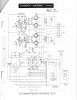

Are you planning to use Tuner/Preamp chassis with this amp? If not, you don't need the mod in this thread but bias adjustment can be made as an individual, per output tube. You will need to check (control) your voltages because without powering the Tuner chassis, they all will be higher.I've just acquired an unmodified Fisher 660a console amp that I plan to modify for standalone use. The 660a supplied power to a separate preamp/tuner chassis and used the preamp heaters for output tube cathode resistance on the amp chassis. In the attached schematic the 660a appears to have a separate transformer tap for the 6 onboard amplifier tubes. (12ax7s and 7591s)
So, is it correct for this newbie to assume that the 'Heater String Cathode Bias System' would not benefit my new 660a as a standalone amplifier?
It looks like someone worked out the resistor values in handwriting to use Amp chassis without Tuner.
Jxmos
Member
Thanks Grindfix - yes I plan to use the amp as a standalone chassis without the original preamp and tuner. I've been making notes on the schematic as I find relevant information on the 660a mods. I found this thread last night and initially thought the mod would apply until I reviewed my schematic.
Thanks for the quick reply. I'll save this link for reference on another project I have on the shelf.
Thanks for the quick reply. I'll save this link for reference on another project I have on the shelf.

I'm in the process of converting a 680-A to Stand Alone.
More info here:
https://audiokarma.org/forums/index...-a-converting-to-stand-alone-question.971194/
More info here:
https://audiokarma.org/forums/index...-a-converting-to-stand-alone-question.971194/

You can use just the resistor. It won't cause any damage to heaters since there aren't any connected
however if you strap it with the zener diodes, it will limit how much the bias point can shift and you may very well end up with a better performing amplifier at the end of the day.
a 12ax7 is basically an 84 ohm resistor, so just multiply that by however many it feeds and round to the closest resistor value. 44v I'm assuming fed 4 heaters, so 336 ohms, or a 330 is the most reasonable value.
I'd personally be tempted to dump all of this and fit it with an EFB regulator on the cathode side. Add both the screen and cathode regulator and you should be able to get more power and lower distortion out of it.
however if you strap it with the zener diodes, it will limit how much the bias point can shift and you may very well end up with a better performing amplifier at the end of the day.
a 12ax7 is basically an 84 ohm resistor, so just multiply that by however many it feeds and round to the closest resistor value. 44v I'm assuming fed 4 heaters, so 336 ohms, or a 330 is the most reasonable value.
I'd personally be tempted to dump all of this and fit it with an EFB regulator on the cathode side. Add both the screen and cathode regulator and you should be able to get more power and lower distortion out of it.

J -- I'm not sure I understand your question: "So, is it correct for this newbie to assume that the 'Heater String Cathode Bias System' would not benefit my new 660a as a standalone amplifier?" As you correctly stated, the 660A used the heaters of the phono preamp and line/tone stage tubes to provide cathode bias for the output tubes, so it's already using the "Heater String Cathode Bias System". However, the 320Ω 20 watt resistor and 15K 1 watt resistors penciled in on the schematic are values I determined some time ago that allows the amplifier to operate properly in stand alone fashion (without the tuner chassis), so I can vouch for their accuracy.
You are also correct that the power transformer does include a separate winding to power the heaters of the tubes on the 660A chassis -- but otherwise, I'm unclear as to what you're asking about the heater string cathode bias design. Now -- if you're asking if the Zener based modification I offered in this thread would be of benefit to your 660A -- absolutely it would. You would simply use the the option of employing four 12 volt 5W Zeners in the string. Then adjust the value of the 320Ω resistor slightly higher to achieve a total cathode current draw of 140 mA. Unless you're using output tubes that require a greater than normal bias voltage to achieve that current draw, this should end up with a bias voltage of around 47 vdc, that the Zeners will quickly clamp if the bias voltage starts to rise under dynamic conditions.
I hope this helps!
Dave
You are also correct that the power transformer does include a separate winding to power the heaters of the tubes on the 660A chassis -- but otherwise, I'm unclear as to what you're asking about the heater string cathode bias design. Now -- if you're asking if the Zener based modification I offered in this thread would be of benefit to your 660A -- absolutely it would. You would simply use the the option of employing four 12 volt 5W Zeners in the string. Then adjust the value of the 320Ω resistor slightly higher to achieve a total cathode current draw of 140 mA. Unless you're using output tubes that require a greater than normal bias voltage to achieve that current draw, this should end up with a bias voltage of around 47 vdc, that the Zeners will quickly clamp if the bias voltage starts to rise under dynamic conditions.
I hope this helps!
Dave
Jxmos
Member
Dave, Thanks for input! You are correct I've been reviewing previous posts to make plans for my new project. Thanks for your contribution!
Yes, my question was whether the Zener based modification would benefit a standalone 660a amplifier. I'll need to read your original description a few more times to get a better understanding. My initial impression of the benefit was related to the impact of the 12ax7 heaters included in the bias circuit. But I see I missed a couple other points you made.
For this case, the 320ohm (or higher) resistor is in place of the heaters shown in your drawing on post #2?
Thanks,
Jeff
Yes, my question was whether the Zener based modification would benefit a standalone 660a amplifier. I'll need to read your original description a few more times to get a better understanding. My initial impression of the benefit was related to the impact of the 12ax7 heaters included in the bias circuit. But I see I missed a couple other points you made.
For this case, the 320ohm (or higher) resistor is in place of the heaters shown in your drawing on post #2?
Thanks,
Jeff