• The move to the new server is done. There are some software and database maintenance updates in process. This has us passing the hat around to help out. We appreciate any donations. Seriously, even a dollar helps. The payment page may be found here - https://www.audiokarma.org/support.html

Improving Fisher's Heater String Cathode Bias System

Yes I wasted hours recently on diagnosing an amp with a variac that was 10v off because the knob had moved on the shaft. 10v on the variac turned to 40v on the b+. A transformer can’t create more voltage than it’s fed.

 
Great thread - and a great mod., which I just did. But I use a vario transformer, already at 208 VAC I get 435 V on the plate. If I go all the way to 230VAC... it will be significantly higher. Is that OK? what do you think of that over-voltage?

What model Fisher are you talking about?
 
A transformer can’t create more voltage than it’s fed.

variacs can actually. Most of them will have a wiring setup for 0-100% or 0-110% or so of input voltage. Usually ends up with full-up output voltage at about 120 or 145 volts AC. I always wire them for 0-100% so I can just wind it all the way up without having to worry about anything. Mine also doesn't have a voltage scale on top. I think it was intended as a panel mount unit, so I run an external voltmeter that gives me actual measured line voltage. I have an ammeter in circuit with a fuse too, just in case.
 
. A transformer can’t create more voltage than it’s fed.
It can’t? Then how did all those vintage CRT based TVs and computer monitor screens light up? How are hundreds of B+ volts created? Because a transformer can in fact create more voltage than the voltage source it’s fed from if it’s designed to do so. A transformer’s turns ratio determines this.

I think what you really mean is that a transformer can’t supply more power to a circuit (a product of volts and amps) than it draws from the power source it is connected to — and it invariably always supplies less because it cannot be 100% efficient.

Dave
 
Last edited:
Ok, back on the X-101-D. At mains 215VAC (checked with DVM), I get 6V on the filament and 444V on the plate. Should I worry about cranking it up to 230VAC, and going above the nominal voltages?

Checking the outputs, one channel is bad. Low output and unstable. Traced it back to the high filter amp stage. The cathode is only 1V compared to the other channel 1.25V. Also, the plate is lower. When I measure AC signal, it jumps a lot like there is a bad connection. With power off I measured all the passive components, all measured ok. Of course I changed the tube, no diff. Can the thick film module be defective in a way causing an unstable signal?
 
higher than proper plate voltage is often caused by low current draw. Weak output tubes, low screen voltage, off-value parts in the cathode string, all possibilities. Its worth figuring out exactly whats going on there.


if plate and cathode voltage are both low, I'd be looking at the power supply end of that section to see if its at the right voltage. High current draw will show low plate and high cathode, low current flow is the opposite. When both are low its usually low supply voltage.

I suppose its not impossible for something in the PEC to fail but it wouldn't be my first thought. Should be able to measure the resistances in that and figure out if that much is good at least. Another quick and dirty test would be to jumper the grids together to see if the problem goes away or moves to both channels. If that changes the behavior, see if setting the mode selector to mono or reverse moves it.
 
As per the service manual output tube plate voltage is 430v. You’re not too far off especially with no load on the tube but you’ll have to measure how much amperage the tubes are drawing. Almost everytime I have a low channel on something that I’ve rebuilt it turns out to be human error. A capacitor lead touching something it’s not supposed to, electrolytic capacitor in backwards. Luckily tube stuff is very forgiving. I’ve also never seen a pec fail since they see such low voltage but there is a guy selling new hand built pec replacements on eBay.
 
also I suppose its worth mentioning, but if you pull the shunt resistor and wire in the zener diodes the current flow through the output tubes is going to be somewhat lower, and that will bump the plate voltage a bit. Exactly how much depends on where you have things set to.

not completely clear what or if mods have been made in this regard.
 
Ok, so the bad stage was caused by a defective C6. Back to the voltage question - with 230VAC mains, I get 476V on the plate and 6,8VAC on the filaments. At least no problem for the 12AX7, but should I worry about anything here?
 
6.8 is higher than ideal. 5% is about as high as you want but truthfully if you can keep it to 6.3 its a good thing
 
right, 6.3 OR 12.6, not the range. Depends on the heater config, 4 and 5 are 12.6 volt, if one side goes to 4+5 together and the other to pin 9, its 6.3 volt.


Honestly I'd be looking to knock the primary side down, it will take care of all of the voltages, not just that one circuit.
 
Thats an efficient way of doing it. Doesn't add a bunch of impedance to the power supply and doesn't waste a lot of power as heat either.
 
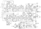
I've implemented this on a Hamlin's 20-20 (aka Trio/Kenwood W-45a) which has a similar series 12ax7 filament setup. In this amp there are only two 12AX7s in the string, so I used two 11V zeners in series, which are then paralleled with the 12AX7 filaments. Otherwise my implementation is similar to the original in this thread. Here's the original schematic for reference. (removed the 300R R76, kept the 40MFD C41)
1787934644316.png

V1 and V2 are the 12AX7's used for EL84 cathode resistance.

One thing I've noticed - since the EL84 cathodes are now clamped at ~ 22V, I can drive them into almost full conduction / significant grid current pretty early. For example, using 4 ohm resistive load on the 4 ohm tap, I observe flat top clipping at 17Vpp (= ~ 9W). At this point, the plate and cathode of the phase inverter are swinging ~ 30 Vpp, and the grid of the EL84 is at 6VDC. So 6V + 30/2 = 21V. And at this point the EL84 cathode is at ~ 22.5VDC.

So I guess we're trading off saving the 12AX7 filaments for reduced power output and hard clipping of the EL84s. Am I understanding this correctly? Should I change anything, e.g. increasing the zeners, or maybe adding some series resistance to the filaments to increase the cathode voltage? Or something else? Or just leave it? The original design is rated at 18W FYI.

Thanks!
 
Back
Top Bottom