• The move to the new server is done. There are some software and database maintenance updates in process. This has us passing the hat around to help out. We appreciate any donations. Seriously, even a dollar helps. The payment page may be found here - https://www.audiokarma.org/support.html

Improving Fisher's Heater String Cathode Bias System

Sorry to start this again but I did the Zener modification to my x-100-b with great results. I just got an x-202-b and was wondering if it works for that too. It uses the 12ax7 heaters for biasing but the circuit looks pretty different with 2 capacitors and diodes almost looks like a voltage doubler circuit.IMG_9939.jpegIMG_9940.jpeg
 
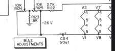
This is a fixed bias set up, not cathode bias. The output tube bias and 12AX7 heaters are supplied by their own PT winding and the full wave rectifiers.
 
yep, fixed bias, supplies negative DC to the grids. The bias supply also provides DC to the heaters for noise reasons.

The clue will be the cathode connection on the output tubes. If it goes straight to ground or through a small (usually less than 20 ohm) resistor, its not cathode biased. The X101 and friends that the zener diode mod applies to run the cathodes of the output tubes through a string of larger value resistors and tube heaters.
 
Hi everyone! On my Fisher X-101-B, I replaced the 920 ohm cathode resistor with the zener string. Both the ground for the heater string and the 4 zeners are connected at a t-strip, with a 10Ω resistor from it to the original ground point. The change really dropped the cathode current. I increased the bias to get 11.7vdc average across the heater string of V1, V6, V2 and V7. That gives me about 48v at the cathode pins, but a current of about 23.5ma. With the bias adjusted to this level, I get 1.4vdc at the test point. This is running it at wall voltage of 122vac, rather than at 117vac on my variac.

Is this a good balance to strike? Could I be doing something wrong that is suppressing the cathode current?


1702854966362.png
 
in stock form, 44 volts / 4 tubes = 11 volts per tube. You've actually got a bit more voltage on each tube now than the stock design would have had, at something like 60% the current. Part of what this does is drop the current through the output tubes by a fair margin, so your results jive with the intended results.
 
is this a 7591 amp or a 7189 amp? I don't know these models particularly well. Looks very good for a 6bq5/7189, probably a little low for a 7591. This should be right about 35ma per-tube on a 7591 based on Dave's original post.

something doesn't seem to quite add up though. With 1.4 volts across 10 ohms thats 140ma. The tubes appear to have individual current numbers, but they add up to considerably less than 100ma. Not sure where the discrepancy is but something is fishy there. There will be a little bit used by the string of resistors where the bias pot is, but it not that much.
 
X101B is 7591's.

Jerry; whats the Zener part # you used??? See post #74 this thread for correct part # for 7591's. Should be 12V 5W. mouser #863-1N5349BG The part # for EL-84's is 833-1N5348B-TP (11V 5W).
 
X101B is 7591's.

Jerry; whats the Zener part # you used??? See post #74 this thread for correct part # for 7591's. Should be 12V 5W. mouser #863-1N5349BG The part # for EL-84's is 833-1N5348B-TP (11V 5W).

I used these: Digikey 4878-1N5349BTR 12V 5W. I've tested it with two sets of 7591's with similar results.
 
Bad multimeter.

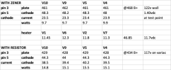
Based on Gadget's reasoning and Larry's question, I went back in to confirm the zeners and look for shorts or other mechanical problems but didn't find any. Next, I switched out probes in case one was giving me trouble. Then I tried a different multimeter and got a much more logical result. I tested again with my cheap multimeter and also got a good result. The readings are below. The meter in question is a Fluke 77 so I tended to trust its results.

Based on these, it looks like I am running cooler, but with higher voltage and less dissipation - the anticipated result of Dave G's awesome zener improvement. Thank you!

It still has a difference between the current of the output tubes at 123ma and the current at the zener string resistor, 136ma.

I'll swap V9 and V5 to match pairs a bit more closely but think I am ok with a a bit under a 5% difference across the 7591's currents?

1702936600261.png
 
:)
Same result with fresh batteries, but that meter is going out of the current measurement rotation.
 
Last edited:
Less than 2ma difference is nothing to sneeze at. Swap V5 and V9, to get a bit more balance between the tubes in a pair. Other than that, button it up, and play the he** out of it!
 
how are you measuring current at each tube? I must be missing something here because the per-tube currents add up to about 120ma, but 1.36 volts across 10 ohms is 136ma. Its a lot closer than before but I'm just curious about the discrepancy.
 
I am measuring output tube current across 10Ω resistors from pin 5 to the cathode bus wire which connects to the zener string and to the heater string. Both of these meet at the t-strip I installed and have a 10Ω resistor to ground. The voltage measurement is taken across that resistor.
 
ah, you have per-tube resistors. That explains it. Discrepancy might just be resistor tolerances then.
 
Great thread - and a great mod., which I just did. But I use a vario transformer, already at 208 VAC I get 435 V on the plate. If I go all the way to 230VAC... it will be significantly higher. Is that OK? what do you think of that over-voltage?
 
what does the heater supply voltage look like? If you get it to 6.3 vac, thats what the mains voltage ought to be. +/= 5% from there is OK, so 6 - 6.6 VAC.
 
What unit??? Agree with Gadget on the non series string heater voltages. Keep them between 6v and 6.6v. The rest of the voltages should then fall into line. Plate voltages will be dependent on what output tube you have. So we need that info too.

Put a meter set to 600vac and see if the dial setting on the vario transformer (variac in the US) is in line with what the meter is reading for output voltage. If it's off see if there is a way to adjust the knob on the shaft so it's reading the same as the meter. (Got a feeling the Vario dial is off kilter). Most of them have a grub screw (up to 2 of them) in the knob that tightenes up against the shaft.
 
Back
Top Bottom