• The move to the new server is done. There are some software and database maintenance updates in process. This has us passing the hat around to help out. We appreciate any donations. Seriously, even a dollar helps. The payment page may be found here - https://www.audiokarma.org/support.html

Improving the Fisher SA-100 with EFB II

The drivers are fed from the B+ rather than the EFB mosfet. Look at the schematic in post 176 above. I also have a "revised" update schematic by Dave dated 1-31-23 that shows the driver stage fed from B+.
View attachment 3836647
Sorry, but I don’t understand why you’re telling me this. Dave has consistently shown it as fed by screen supply on the clone and from the plate supply on the real Sa-100. The 2023 schematic you just posted shows driver/inverter fed by screen mosfet, not plate B+. It’s true that once Dave added the 8.2K resistor (the original design did not have) it allows some current to bypass the MOSFET, but there’s still 339v at that point that’s controlled by EFB. But I do appreciate you posting it - I had not found that.
 
Last edited:
I guess I misread the clone schematic. It didn't/doesn't seem like the drivers stages should be fed by the EFB transistor so I thought it could be a mistake in the schematic but I looked back at the earlier versions of the clone schematic it is clear that the front end is fed from the mosfet. I don't think that's been done in any of the other EFB installs that I've seen so I had that notion in my brain.

sorry,
John
 
…… I don't think that's been done in any of the other EFB installs that I've seen…….
I agree - every other EFB implementation that I’ve seen has not taken the downstream power drops from the MOSFET. That’s why I was asking about it so much to understand if there was a special reason for doing it that way.
 
I was really just wondering if he purposely did the driver/inverter sources differently for a reason that I needed to consider,
I don't understand what you're asking here. The driver/inverter is not sourced differently, its fed via a drop resistor. EFB has nothing to do with that power supply node.


unless you're looking at a schematic other than the one I am.
 
I don't understand what you're asking here. The driver/inverter is not sourced differently, its fed via a drop resistor. EFB has nothing to do with that power supply node.


unless you're looking at a schematic other than the one I am.
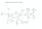
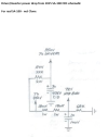
There is a separate schematic for the "clone" EFB power supply (dated 2023) and the "real" SA-100 EFB power supply (dated 2025). They differ mostly because the real SA-100 uses standard negative fixed grid bias (prior to EFB mods) and the clone uses cathode bias because the PT Dave happened to have on hand did not have a bias tap. Here are two snippets from each schematic showing the source for the driver/inverter power. The real SA-100 EFB mods show the power coming directly from the non-MOSFET controlled 450v B+. The clone power supply shows the driver/inverter power coming off of the 339v screen supply which is under control of the MOSFET. It might appear to come directly off of the 447v B+ through the 510Ω and 8.2K dropping resistors, but Dave added that 8.2K resistor on the latest version to shunt a portion of the current around the MOSFET but ultimately the MOSFET is still controlling the voltage of the screens and therefore everything downstream from there.

2023 Clone Snippet.png2025 Snippet.png
 
Back
Top Bottom