


You are using an out of date browser. It may not display this or other websites correctly.
You should upgrade or use an alternative browser.
You should upgrade or use an alternative browser.
Improving the Fisher SA-100 with EFB II
- Thread starter dcgillespie
- Start date


I believe the 72V is applied to the heaters at the specified junction (instead of the chassis ground) to elevate the heaters with DC voltage and thereby reduce the cathode-to-heater DC voltage difference. Applying 72VDC to the cathodes would cause the tubes to operate incorrectly.
Try this one, its a higher rating...Thanks, Dave!
I noticed Mouser marked STF10NK50Z unavailable and obsolete. I would be good to have a fresh part number.
STF12NK60Z

exactly. Its to keep the heater-cathode voltage reasonable. As-built the phase inverter is 105 volts H-K, over the 100 volt limit for a 12AX7.I believe the 72V is applied to the heaters at the specified junction (instead of the chassis ground) to elevate the heaters with DC voltage and thereby reduce the cathode-to-heater DC voltage difference. Applying 72VDC to the cathodes would cause the tubes to operate incorrectly.
the amp I recently did has them biased up about 50 volts for the same reason. Cathode of the inverter runs also a little over 100 volts.
So attached to the Y lead?I believe the 72V is applied to the heaters at the specified junction (instead of the chassis ground) to elevate the heaters with DC voltage and thereby reduce the cathode-to-heater DC voltage difference. Applying 72VDC to the cathodes would cause the tubes to operate incorrectly.
Here's a BOM I started in Mouser, if you have any comments, I can update the BOM.
Mouser BOM- Version 1

I would say connect to the center tap between R57 & R58 now grounded (between Y and Z)So attached to the Y lead?
Thanks for your work on the BOM. They are very nice, but I think in this position it is OK to use a less expensive film capacitors (than the C-D 942C series on the 0.47 uF.)
Last edited:
Yeah, it wasn't clear but I assumed the ground is lifted between R57&R58. I never knew there were max values on Cathode to heater voltages on IDHT tubes. Just noticed the high voltage on the phase inverter...makes sense now. Its more of an arc over issue than a performance issue from what I can tell.I would say connect to the center tap between R57 & R58 now grounded (between Y and Z)
Thanks for your work on the BOM. They are very nice, but I think in this position it is OK to use a less expensive film capacitors (than the C-D 942C series on the 0.47 uF.)
What is everyone seeing for power output with the EFB circuit?
I'm measuring a stock unit at 14wpc @ 1% THD but I think the amp needs some more caps, last guy just brought it to life with a few caps and resistors, it needs more.
Tubes might be about 65%.
Updated BOM with the less expensive cap. $13 in tariffs :-(
Last edited:
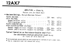
strictly speaking by this datasheet at least its not outside of tolerable limits. Heater here would be negative relative to cathode since its grounded in stock form and the cathode is +105v or whatever but the higher that difference, the more prone things are to insulation failure and noise. Most common tubes are rated 100v H-K difference, or sometimes its 100v DC plus AC signal peaks for both positive and negative. This is probably going to see ballpark of another 15 volts or so peak AC, so ~120v worst case.
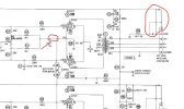
In Sams Photofact nomenclature, the dotted lines indicate an alternative connection. Basically some are like the solid line, some are like the dotted. The X means "delete" so if its wired like the solid line indicates, the dotted line will not be connected and vise-versa.
so for that one on the right either the 47k off the balance pot go to ground, or they go to the cathode of the 7189, but not both.
so for that one on the right either the 47k off the balance pot go to ground, or they go to the cathode of the 7189, but not both.
About 90% completed, I had to spend some time on the grounding yesterday.
The connection points to the chassis were anywhere from 4 ohms to 15 ohms apart. Also found several power resistors +10% over spec.
Installing screen resistors and debating on whether to move the bias test points and bias outputs separately like Dave did. Not sure there's anything to gain unless you added bias pots for each tube. I think they need to be somewhat matched in pairs.
The connection points to the chassis were anywhere from 4 ohms to 15 ohms apart. Also found several power resistors +10% over spec.
Installing screen resistors and debating on whether to move the bias test points and bias outputs separately like Dave did. Not sure there's anything to gain unless you added bias pots for each tube. I think they need to be somewhat matched in pairs.
I ordered up the parts and finished up the wiring. Man, that little amp is busy underneath--cramped work environment! Had to move some of the screen grid components (including the MOSFET) to accommodate the Hammond filter choke, but do-able. About to do the double/triple check on wiring and power up next couple days. I will report results, compare voltages with the prior EFB(tm) installation and do some audio measurement on my prior upgrade thread.
Dave
Dave
Fisher SA-100 Comparison--Original vs. Clone
I notice that the circuit values in the SA-100 clone are quite different than the original Fisher. Could this have any effect on the overall THD of the amp? I've tried several different pair of output tubes but they all give similar distortion figures after I adjust the AC balance for minimum...
audiokarma.org

take pics!!I ordered up the parts and finished up the wiring. Man, that little amp is busy underneath--cramped work environment! Had to move some of the screen grid components (including the MOSFET) to accommodate the Hammond filter choke, but do-able. About to do the double/triple check on wiring and power up next couple days. I will report results, compare voltages with the prior EFB(tm) installation and do some audio measurement on my prior upgrade thread.
Dave
Fisher SA-100 Comparison--Original vs. Clone
I notice that the circuit values in the SA-100 clone are quite different than the original Fisher. Could this have any effect on the overall THD of the amp? I've tried several different pair of output tubes but they all give similar distortion figures after I adjust the AC balance for minimum...audiokarma.org
This is before the heater mod
Still need to clean up mess from previous repairs
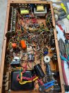
Still need to clean up mess from previous repairs

Can someone please provide the latest schematics for the clone SA-100, the power supply, and the newest EFB schematic for it as well? I plan to build using SS rectification - my PT has 640vac CT secondaries. I'm not sure how close I can get to the specified plate B+ with an adjustment to (or even elimination of) the first dropping resistor. The secondary is rated at 400mA and I plan to use a pair of fast diodes and a separate choke for each channel, so that should all help to minimize the voltage drop. There is also both a 120v and 125v primary, so I can use the 120 to bump it up a little as long as the 6.3 remains acceptable. I realize that EFB will maintain the proper relationship between plates, screens, and grid, but how critical is the 447vdc plate, and if I have less, will the recommended 25mA cathode quiescent current no longer provide optimal performance?

@tekuhn,
I agree with nerdorama that you probably could make your power transformer work in the modified SA-100; play with PSUD2 to see what you can expect. With the higher current rating of your transformer and SS diodes, you will have a “stiffer” supply than OEM, with less sag at higher demands. So if your quiescent plate supply ends up at say 425 Vdc rather than 445 Vdc you are still only about 5% out, and less so under full load. I would not worry about changing the bias current in the output tubes, but if you do you could increase it slightly, keeping actual dissipation similar to Dave’s 9.5 watts per tube.
This thread has the latest modification update from Dave Gillespie in post #138. There is a schematic of the original here:
What output transformers are you planning to use? Good luck with your project.
I agree with nerdorama that you probably could make your power transformer work in the modified SA-100; play with PSUD2 to see what you can expect. With the higher current rating of your transformer and SS diodes, you will have a “stiffer” supply than OEM, with less sag at higher demands. So if your quiescent plate supply ends up at say 425 Vdc rather than 445 Vdc you are still only about 5% out, and less so under full load. I would not worry about changing the bias current in the output tubes, but if you do you could increase it slightly, keeping actual dissipation similar to Dave’s 9.5 watts per tube.
This thread has the latest modification update from Dave Gillespie in post #138. There is a schematic of the original here:
What output transformers are you planning to use? Good luck with your project.