• The move to the new server is done. There are some software and database maintenance updates in process. This has us passing the hat around to help out. We appreciate any donations. Seriously, even a dollar helps. The payment page may be found here - https://www.audiokarma.org/support.html

Improving the Fisher SA-100 with EFB II

I have a pair of the same Stancor 51-58 OT's that Dave used. I'm pretty sure that if my idle plate B+ is reasonably close, that EFB will maintain the screen and grid voltages to keep the proper relationship and I can still set bias for the same recommended idle current. Hopefully I can get Dave to comment so I will know for sure.

The schematic in post #138 says it's for the SA-100 and not the clone, so I wasn't sure if there are any differences....
 
You did say you are planning a clone SA-100, but since this is the thread for the “real SA-100 modification”, not the SA-100 clone, I thought you meant the “ real modified SA-100”. My mistake. Apologies.

The amplifier that Dave described elsewhere in the SA-100 clone thread used a Fisher power transformer with the Stancor 51-58 output transformers. His PT did not have a tap for negative grid bias of the power tubes and therefore used the EFB cathode bias scheme, which consumes some 12-15 Volts of the B+. If you your B+ is low to begin with you might consider using the grid bias scheme Dave used in this thread (post #138), if you can provide the negative bias from your PT or separate tranny.
 
That's my fault - my question probably belonged on the clone thread. The PT secondary does have a 50vac tap for negative bias so I can build off of that. I guess really the only question I have, regardless of EFB implementation, is whether the 25mA idle current per tube is still optimal if my idle plate voltage is lower.
 
OK, I do see what you are talking about - on his clone I see the positive voltage cathode regulation and a lower voltage, but still positive regulation on the grids. I'm actually more familiar with the method shown in the #138 schematic as it's essentially the method used on the Fisher 400 which I have done before. For my project it would make sense to use the newer version since I have a bias tap and can provide a negative voltage for the grids. Only possible "negative" would be the substantially less filtered 1/2 rectified grid bias source.
 
Hopefully Dave will spot your question and provide guidance. Meanwhile, if your PT has the bias tap like the “real SA-100” I would suggest you follow the grid bias EFB scheme Dave provided in post #138. That will maximize available high voltage across the output tubes compared to the scheme used in the SA-100 clone thread using partial cathode EFB.

Build it and see what B+ you end up with. If it is below 420 Vdc or so you might consider raising the idle current of the output tube just a bit, but keep the dissipation below 9.5 Watt, as Dave recommended at these elevated plate voltages. There is probably no “magic’ in the 25 ma, just good engineering compromises to balance performance versus burning up output tubes.

Please keep us informed of your progress.
 
Only possible "negative" would be the substantially less filtered 1/2 rectified grid bias source.
But with a 50v tap you will have some excess voltage so you can use a couple stages of RC filtering. And as long as you use a reasonably well matched set out output tubes you will get some cancellation of residual noise in the output transformer. And don’t forget that the EFB circuit gives filtering to the bias voltage.
 
There is probably no “magic’ in the 25 ma, just good engineering compromises to balance performance versus burning up output tubes.
Dave is able to determine an optimal bias current the will give improved performance. He has also said in some other thread that you can use the data sheet or factory bias and get improved performance too. I would probably go with @spantou01 recommendation and set your bias for a matching dissipation level. I don’t thing you will be very much below his B+ anyway and the screen voltage will have a larger effect on current.
 
Good points. I think I’ll be able to get close on B+ too, but since I have no way to measure distortion it would be nice to know where to start.
 
I would take the B+ you get and set the screen voltage per Dave’s design and then pick a bias current either matching the 25mA of Dave’s or slightly adjusting to give the same total dissipation.
 
Agreed. I expect your B+ should work out just fine, probably 425-435 Vdc.

With the control grid bias EFB of the SA-100 mod used instead of the partial cathode bias EFB for the clone, your target B+ is about 432 Vdc, compared to 447 Vdc, since the cathodes (of the power tubes) now sit at ground, not at 15 Vdc as with the cathode bias EFB.
 
More questions related to EFB and elevating the heater center tap....

Since I'm building the "clone" audio circuit, but using a PT with a 50v bias tap, I am combining some aspects of both designs. I suspect I have some freedom to do things either way, but would love input - especially from Dave himself!

- The clone EFB-II implementation takes the driver and inverter power off of the MOSFET controlled screen supply, but the standard EFB circuit for the stock SA-100 takes the driver and inverter power off of the unregulated plate supply and also derives a 72V heater bias from this same source. Is there an advantage to one method over the other? The additional current draw of the driver/inverter circuits is negligible as far as the MOSFET is concerned, so is there an advantage to having the driver and inverter supply controlled by EFB?

- Is the recommended heater lift bias different for each design since one uses 7247 tubes and the other uses ECC83 and 6CG7 tubes? The SA-100 EFB schematic shows 72v and the clone schematic shows 43v.

Thanks in advance....
 
It would be nice to have definitive input from @dcgillespie, but meanwhile here are some thoughts.

1. Where to tap HV supply for the driver and inverter. I don’t think it make much difference, if any. The MOSFET does not regulate, it simply sources a low impedance screen grid supply that follows the B+ proportionally. The associated capacitance provides some additional smoothing, so I think after the MOSFET is (slightly) preferred. And it worked well in the many AS-100 clone that followed the design.

2. Both 7247 and 12AX7 drivers feature 100Vdc max for heater positive with respect to cathode. The inverter triode in both 7247 and 6CG7 allows 200 Vdc heater negative w.r.t. cathode. In the AS-100 and clone the driver cathode is close to ground and inverter cathode sits at 100 Vdc. To me 43 Vdc lift puts the driver at a good spot in the middle of its comfort zone, while 72 Vdc is getting close to the 100 Vdc max. I don’t know why Fisher designers had the 7247 heaters at 72 Vdc; it would be interesting to hear Dave’s explanation. But I believe a 43 V lift works well for the AS-100 clone, just as Dave designed it.
 
Thanks for the reply.

I realize the mosfet doesn’t regulate the voltage which is why I was careful to say that it “controlled” the screen voltage. I tend to agree there’s no reason not to derive the power for the driver/inverter from there and probably will.

I didn’t know the stock SA-100 lifted the heaters to 72v - I got that number from Dave’s 2025 EFB schematic so I assumed he specified it. It’s interesting he chose to leave it at 72v but dropped it to 43v on his clone circuit. I think it’s safe to say he gave careful consideration to his own design and it makes sense to follow it.
 
A correction. I assumed Dave “inherited” the 72 Vdc heater lift from the Fisher SA-100 design. After checking it appears that they have not applied any heater lift in the original SA-100, based on the schematic available to me. It appears that the 72 Vdc lift originated with Dave’s modification of the SA-100.
 
Ok thanks. I assumed he had come up with both numbers and thought perhaps there was a difference between the tubes. Suspect either will work fine but will go with 43v unless I hear differently.
 
maybe we're looking at different things here, but it doesn't appear to me that the drivers are fed from the EFB regulator based on this, which appears to be the most-current schematic

1789401211264.png

Driver stuff feeds out of the middle bit above the two mosfets, where it is marked 350V To Drivers.

This section has two other connections. An input from he 450V source that feeds the output transformers, immediately downstream of the choke, plus a 72V output to bias-up the heaters.

The driver power supply appears to be a conventional RC filter stage as would have been used originally. Drop through R44, filtered with C1D. The other parts in there are for the heater elevation.

that all appears consistent with what I've seen on other EFB screen regulator arrangements.
 
Hi Gadget - I understand all of that and I do have that schematic. It is for the actual SA-100. I am building the clone amp. Since the PT I'm using has a 50v bias tap, I prefer to build the EFB™ implementation that ties the cathodes to ground and controls the grid and screen voltages only so I'm making a hybrid power supply of the two. As you said, the above circuit takes the driver/inverter power off of the non-EFB™ controlled plate supply, however, if you look at Dave's clone EFB™ power supply, he takes it from the EFB™-controlled screen source.

I was really just wondering if he purposely did the driver/inverter sources differently for a reason that I needed to consider, and also why he chose to elevate the heaters +72v on the SA-100 and +43 on the clone.

Dave has reviewed my preliminary schematics and sees no reason not to proceed with the knowledge that I might well need to tweak dropping resistors once I see actual working voltages.

Thanks!
 
Last edited:
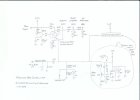
The drivers are fed from the B+ rather than the EFB mosfet. Look at the schematic in post 176 above. I also have a "revised" update schematic by Dave dated 1-31-23 that shows the driver stage fed from B+.
SA-100 Clone Update EFB.jpg
 
Back
Top Bottom