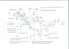
Well geez, it's been nearly what, 13 years since I published the EFB™ modification for the Fisher SA-100 -- but like all things that change with time, so it is with this modification as well. As far as EFB action goes, the new version of the modification doesn't cause it to work any better than when first published, but there are a number of worthwhile improvements resulting from the new version none the less. Collectively they include:
1. Use of a better mosfet family with regards to mounting. The new mosfet is plastic, so it can simply be bolted to any convenient chassis hole for heat sinking purposes. With nothing more than a nut and bolt and a little dab of thermal grease then, you're good to go. The new mosfet also eliminates the need for the external Zener diode used in the original modification.
2. The mosfet still dissipates about 1 watt under quiescent conditions like before, but now only about half of what it did before under a full continuous boil in both channels (~ 2 watts).
3. In the spirit of bullet proofing the design -- similar to that which I did some time ago for the cathode regulator version of EFB -- there is now more protection built in for the mosfet as well as for the EFB bias supply regulator. There have been no known failures of these components with the original modification, but more protection is always good in case a tube decides to go sideways.
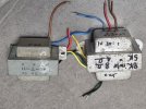
4. The new design also includes the use of a small Hammond 156R choke that can be mounted under the chassis on the end side panel near the output terminal strips. The choke can actually handle the full power current draw in both channels simultaneously, and makes itself known in two ways: At turn on, there is now no hint of 120 Hz hum as the output tubes warm up and balance out their current draw to cancel out the significant 120 Hz ripple voltage present at the OPT CT leads in the stock design. As well, less ripple in the B+ supply translates into less interaction with the audio signal passing through the output stage, and therefore reduces distortion.
5. Output stage plate voltage is elevated slightly as a result of the revised modification, which increases power output slightly -- on top of the increase already produced from the original EFB modification. EFB quiescent current draw remains the same, with the output tube plates dissipating little more than 9.5 watts each. This is just under 80% of the Design Center 12 watt Pd rating for the tubes.
Other changes on the revised schematic include:
A. The new schematic is more complete, now showing the driver stage B+ supply components as well.
B. The new schematic now specifies the CE C30X4-475 as the replacement can cap of choice. The original can cap was only rated for 450 volts, and therefore could also be rated for 85˚C operation. But this voltage rating is inadequate with today's higher line voltages and reduced current draw afforded by installation of the EFB modification. It is tempting to use a modern 525 volt can, but such cans are only rated for 55˚C operation, and therefore would not be advisable for use with the stock design since the stock amplifier runs
quite warm. With the EFB modification however, the amplifier runs significantly cooler, allowing the 65˚C rating of the suggested can cap to operate with adequate temperature reserve.
C. The revised modification recommends the addition of a CL-80 inrush current limiter be installed between the AC line cord and the fuse post.
D. Finally, the revised modification also includes a heater bias circuit as the design is quite hard on the heater/cathode insulation in the phase inverter section of the driver tube. Even the official Fisher schematic of the SA-100 shows a heater/cathode voltage differential of 110 vdc, exceeding the Design Maximum rating for the 12DW7/7247 tube by 10%. Sams indicates it is also exceeded, although by only 5%, but both of these figures are based on operation from 117 vac. With the heater bias in place, the heater/cathode junction operates at only 72% of the rated allowable maximum voltage -- and this is based on operation from today's higher line voltages, and with the EFB modification in place.
For those lucky enough to own a Fisher SA-100, they well know that it is one of the best sounding 6BQ5/EL84 amplifiers ever produced. EFB doesn't change the character of the SA-100, but simply allows the amplifier to supply more of it, with longer output tube life, lower distortion, and cooler operation. And now, the modification itself is even better protected as well.
Happy listening!
Dave
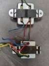
Below -- Shows where the Hammond choke can be mounded under the chassis. The inner most mount screw passes through a cooling hole, while the outer most mounting screw requires a single small hole to be drilled in the side of the chassis to facilitate the screw:

The revised modification: