• The move to the new server is done. There are some software and database maintenance updates in process. This has us passing the hat around to help out. We appreciate any donations. Seriously, even a dollar helps. The payment page may be found here - https://www.audiokarma.org/support.html

Improving the Fisher SA-100 with EFB II

Ha. Yep. Although when I was taking it apart I did find a bad ground connection in the B dc balance circuit, so I'm happy that got double checked.

So now that my histrionics are over I have a nice bias of 24ma. Sounds good. I'm going to adjust the dropping resistors as it brought the B+ up to 456 and the cathode resistors on the second half of the driver tubes are a little out of spec, I'll find some nice Allen Bradlys.
And my .01% cathode resistors came so I can install those.
 
Thanks so much Dave.
I will keep you updated.

Now, for the real reason I was getting pissy with myself. While I was tearing my hair out I knocked it over and smashed a perfectly good Japanese GZ34 and broke the tip off a mullard 7247. That's when the JJs came out for the rest of the testing. Doh!
 
notben,
I've been lurking.
We've all dropped tubes n'stuff. I dropped a 5R4GB rectifier just Thursday and it smashed the glass.

It has been fun watching this project.
 
Thanks. I can't wait to really listen to Dave's circuit. I will run it through a few of my PI speakers, but I will be interested in trying them on my Magnepan MMGs. Not for regular listening, but the SA100 can handle the 4 ohm impedance and I would bet the screen stability should keep the bass from distorting at a nice listening level. I was surprised how well they did stock, and I run normally run those with a modded Phase Linear 400 or a Bedini 250. Should be fun.

-Ben
 
You'll find a lot more grunt with that circuit.

It's almost like more power, but more like more control, poise, and grace under pressure than outright uncontrolled boisterousness.
 
I have spent some quality time with my newly modified SA100 with the ESBII installed.
That is some nice stuff. Great circuit Dave. Thank you so much for sharing and helping.

Through my PI 2 speakers everything is just a bit better. Absolutely no mud or smearing in the mid-bass. I am running another pair of Mullard 7247's and a set of 6P14P-eb 7189's from Jim McShane that have been in the amp for a good two years.

The fun test was to hook up the 4ohm output to my Magnepan MMG's. It held it together very nicely at good listening levels for most music. The mastering of the source was much more critical in this setup. Some of the albums I tested are a little more compressed and require more from the power supply ( Jeff Beck Blow by Blow, Thievery Corporation - radio retaliation) and also some good New Orleans brass band music (Soul Rebels, Hot 8) that have a lot of Tuba and crisp heavy bass along with a full brass ensemble; but it helps me judge the current demands of the MMG's.
Miles Davis Quintet recordings sound as detailed and powerful as some of my SS amps if I am sitting about 6.5' from the speakers. When I tried to get similar SPL's further back at a couch at 12' from the setup, some of the recordings would begin to distort because I had to turn up the gain on my preamp higher than I would normally like -- tested with both a Bottlehead FPIII, and a homebrew 6SN7 pre.

But with more appropriate speakers like my Pi2's or my Paradigm Titan v.5 or my Fostex 6" Sigma horns, their was nothing I couldn't throw at the amp/setup.
Can't wait to finish my Pi4's to try out.
And to tube roll with some matched quads of Sylvania black plate 7189's and some Heerlen D getter EL84's (rX1 or rX3, that can handle 7189 like voltages, especially now with the lower voltage and regulated screens due to the ESBII)
:thmbsp::thmbsp:
 
Not -- Thanks for the detailed report! Magnepans are very difficult speakers to drive, so you were really giving your SA-100 a workout with them. Its good to hear how well your amp did driving them. With the operating conditions now employed in the output stage, you should be able to use any quality 6BQ5 in your rolling exercises.

Good luck with it!

Dave
 
Slight thread necromancy here, Dave. I've (finally) managed to find a second Stancor A-8054 output transformer - a massive beast with a 9k primary impedance. Think a pair of these would work well in this circuit, or is the SA-100 looking for a lower primary (in spite of the optimal EL84 preference) in the 6-7k range?

Thanks,

-D
 
To produce the rated performance, the primary impedance needs to be around 7.5K - 7.8K. While a 9K impedance would work, power output will be reduced, and, it would require a new workup of the NFB and stability networks to achieve best performance.

Wasn't the A-8054 originally intended for a Williamson application?

Dave
 
To produce the rated performance, the primary impedance needs to be around 7.5K - 7.8K. While a 9K impedance would work, power output will be reduced, and, it would require a new workup of the NFB and stability networks to achieve best performance.

Wasn't the A-8054 originally intended for a Williamson application?

Dave

Yep. However, given all I've heard about how finicky 807-based Williamson circuits are to get right, I'm a little leery of going down that route. If I were to do a stereo Williamson, I'd need something like 800VCT @ 400mA for the HV to power it...

If these rumors are hogwash, then maybe it is something I'd entertain...but I'd still need to find that power transformer (and choke).

-D
 
Yep. However, given all I've heard about how finicky 807-based Williamson circuits are to get right, I'm a little leery of going down that route. If I were to do a stereo Williamson, I'd need something like 800VCT @ 400mA for the HV to power it...

If these rumors are hogwash, then maybe it is something I'd entertain...but I'd still need to find that power transformer (and choke).

-D

I'm starting to think *maybe* doing an 807 Williamson might be the way to go...although I'm not sure if I'm going to try mono-block or stereo.

-D
 
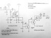
Although old and dormant for some time this thread is one of those “Oldies but goodies” by Dave Gillespie. I was rereading it in preparation of building my own AS-100 clone with a Heathkit AA-100 transformer set, and noticed that the B+ and EFB regulated screen supply is given here in the schematic sketch below as 445V and 334V respectively. These voltages are identical to the AS-100 clone’s voltages.

However, I noticed the original Fisher AS-100 manual lists B+ and screen supply voltage as 390V and 290V respectively.

Could someone shed some light on this discrepancy? I could not find any reference to the B+ Dave used in this thread on the rebuilding of Fisher AS-100. I apologize if I missed it. Below are a few relevant excerpts of the Epilog post #30

Epilog

With this post, I have provided a schematic of the EFB(tm) modifications installed in the SA-100. I will go over the modifications in a moment, but first, some general comments.
<snip>

Another area of opportunity in the SA-100 -- and likely represents the biggest difference between the clone and the EFB modified SA-100, is that of the basic power supply. The power transformer and rectifier are capable enough, but the healthy choke used in the clone version represents a significant advantage in the war on distortion over the power supply of the stock design. While the simple series dropping resistor used in the SA-100 provides filtering enough for normal listening purposes, its limitations show up in the slightly higher distortion levels produced, and particularly so at the lowest frequencies. The level of AC ripple current present under high demand conditions at the OPT CT is significant in the SA-100 (over 10 vac). With the clone, it remains negligible in high demand conditions over the entire audio spectrum, which allows for lower distortion levels to be achieved due to the elimination of this influence.

The problem is space. This little amplifier has no room for the choke I chose for the clone. I then thought of using a smaller choke to supply just the screen and driver circuits, but the EFB screen regulator provides significant filtration by itself, making any gains from this approach nil.<snip>

These two areas then represent the biggest difference that exists now between the clone and modified SA-100. Both units sound superb. I do give the edge to the clone version however, as I do believe the approach used in that unit to generate absolute stability allows for a more open sound if not certainly its extended bandwidth. I would again emphasize that both of these amplifiers sound like 6BQ5 amps on steroids. They just have that extra punch enjoyed by the 7591 crowd. Also, the degree to how much cooler the SA-100 operates now cannot be overstated. The reduction in heat output is more than significant -- which is important when cramming so much horsepower into so little space.

With regards to the EFB regulator circuits themselves, the screen regulator is almost a direct copy of the regulator I designed for my clone version, without the voltage adjustment control I used on that version. Its operation is very simple. The output stage in the original SA-100 operates as almost a text book copy of the conditions published by RCA for a 24 watt output level, where in the screens operate at 75% of the plate voltage.<snip>

Dave

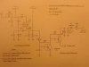
upload_2023-3-10_15-11-17.jpeg
 
spantou. Edit the picture so it shows up as a full size. Right now it's locked as a preview or (I can't remember the word I want to use). Unlock it to full size, please.
 
Larry,
I expect it's this one, but let's let spantou confirm. I used this circuit to provide EFB (tm) to my SA-100 restoration.
Dave

SA-100 EFB.jpg
 
Yup! That’s the one. Sorry about attaching the thumbnail only.

BTW, @Dave451, how did you get the schematic so much lighter. On my computer it looks like it is drawn on brown parchment paper. Thanks for the better copy!

The question is about the difference in specification of the original Fisher schematic of B+ of 390V and this B+ of 445V, with similar differences in screen supply - from the same power transformer. As far as I could see the R42 & R43 (voltages dropping resistors after the rectifier) remained intact in Dave’s rebuild of the AS-100 described in this thread.
 
Last edited:
Voltages in my SA-100 modified with Dave's EFB(tm) with the tubes biased at 24mA per tube (as he recommended)were as follows:

Power supply:
Exit 5AR4: 440VDC
Plate Supply from EFB: 424VDC
Screen supply from EFB: 313VDC
Bias supply from EFB: -32VDC

Output Tubes (EL84M):

Plates: 423VDC
Screen Grids: 313VDC
Control Grids: -13.1 to -13.4 VDC
Cathodes: 240mV

As Dave mentioned, these voltages run a bit higher than stock because the output tubes are biased at 24mA per tube, compared to 31mA per tube stock: 23% reduction. This unloads the power supply a bit and causes all voltages to rise, in lock step of course because of EFB(tm).
 
Thank you! Very helpful. I wonder about the 440Vdc after the rectifier; Fisher manual says 410Vdc. I guess they listed it under load.

I’m building a Fisher AS-100 clone using the Heathkit AA-100 transformer set, including the original power transformer that features a bias tap. The supply voltages should be close enough that I will proceed and use Dave G’s EFB schematic that you reposted in #94, instead of the EFB cathode bias used in the original clone article by Dave G.
 
Last edited:
As for the 440 vs 410, this is also likely due to the PS being less loaded with the reduced output tube current draw with EFB(tm).
 
Hi all, I am getting ready to perform this to a recent pickup of an SA-100, but the FQP9N50C was not available, but was able to get a FQP9N90C. Is this a suitable replacement for the earlier 50C part? Thanks!
 
Back
Top Bottom