• The move to the new server is done. There are some software and database maintenance updates in process. This has us passing the hat around to help out. We appreciate any donations. Seriously, even a dollar helps. The payment page may be found here - https://www.audiokarma.org/support.html

Improving the Fisher SA-100 with EFB II

Getting Grounded

OK. Now that THAT little issue is taken care of, I am back to somewhat north of square one.

The grounding issue looked to be quite problematic, virtually requiring a near rebuild, which I have not budgeted the time for. So, an alternative approach was tried that has every appearance of being completely successful.

I used a dab of Cramolin (Red) on all the mechanical connections to the chassis (which are riveted), and let it soak for 24 hours. I followed that up by using a rivet punch to re-sink each rivet used for electromechanical connections to the chassis. The result is no detectable ground resistance at all anymore at any grounding point -- which I consider significant. Because it saved an incredible amount of time, and worked extremely well, I though I would pass it on........

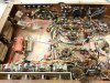
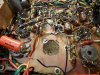
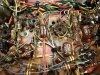
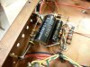
So, the pics show the current status:

1. The unit's original wiring for posterity.

2. The old screen wiring coming out.

3. The old can cap removed.

4. New matched individual 10 ohm cathode resistors for each output tube connected to the newly created TPs on the output terminal strips.

5. Matched 100 ohm screen stability resistors installed at each output tube. Also note at the bottom of the pic that the new can cap has been installed as well.

So, current status has the old damping controls circuits removed, the old cathode wiring removed and new individual cathode current sensing resistors installed with four new TPs for measurement, the old screen wiring removed and new wiring and individual screen stability resistors installed, the old can cap removed and a new cap installed, and all the grounding issues resolved. A bunch of work, but for performance measurement purposes, still basically the stock design, albeit with some nice upgrade features added.

The output tubes have now been reinstalled, the unit fired up, and the bias properly set and balanced. Once again, it is ready for the test bench.

Tomorrow, I will retest, document, and post the results here, and then maybe I can finally get back to (or on with) the installation of EFB II.

While I'm at it, I'll count my blessings that I did not endure and lose what so many have in the northeast. I hope the same for all of you as well, and a speedy recovery for those that have.

Dave
 

Attachments

  • SAM_0022.jpg
    SAM_0022.jpg
    110.6 KB · Views: 388
  • SAM_0028.jpg
    SAM_0028.jpg
    115.8 KB · Views: 341
  • SAM_0027.jpg
    SAM_0027.jpg
    114.7 KB · Views: 331
  • SAM_0030.jpg
    SAM_0030.jpg
    79.5 KB · Views: 355
  • SAM_0031.jpg
    SAM_0031.jpg
    130.6 KB · Views: 365
A thorough retest of the Fisher SA-100 now with its grounding system repaired, a new can cap installed, as well as the other upgrades mentioned earlier.

Two observations were made:

Sonically, the unit is decidedly quieter now -- not quite as quiet as the clone version, but notably quiet enough through my Cornwalls. Program material is more focused as well now.

From a measurement standpoint. Grounding issues -- left to their extreme -- can cause really weird problems. In this case however, they were hardly so extreme as to cause any obvious problems during the first testing session, but with the grounds repaired, even the measurements are more "focused" (if you will) as well. That is, the performance of both channels is nearly identical now, where as before, differences were noted, but hardly so great as to suspect anything more than normal component tolerances. So, the effort was well worth it.

Some numbers deteriorated slightly, some were improved slightly, while some were basically unchanged. In any event however, I have a high degree of confidence in their accuracy now.

The snap shot of performance is now: At 1 kHz, each channel driven individually produces 20 watts RMS. With both channels driven, each channel can achieve 16 watts at this frequency. At 20 Hz, each channel individually produces just over 15 watts RMS, while driven together, this drops to 13.7 watts in each channel. At 20 kHz, each channel driven individually produces 19 watts RMS, while driven together, this drops to 15.5 watts.

Distortion wise, each channel individually could produce about 8.8 watts RMS at 20 Hz, at 1% THD, at 1 kHz, 17 watts in each channel individually produced about .13% THD, while at 20 kHz, each channel individually produced about .77% THD. When both channels were driven to 16 watts at 1 kHz (onset of clipping), distortion rose to .4% THD.

Frequency response remained basically unchanged at +0/-.5db to 37 kHz, and stability in both channels was absolute. This stability performance was getting to be a common achievement at the end of the 50's, but surely took its toll on frequency response, with a number that in the mid 50's would have been decried as very poor -- but also produced very poor stability as well.

1.2 vac was required to achieve full power output in both channels.

The optimum quiescent cathode current setting remained at 31 ma per tube.

So against this stock performance, what can the installation of EFB II expect to achieve? The stated goals include:

1. An increase in power output to (hopefully) 20 watts RMS per channel with both channels driven from 25 Hz to 20 kHz. This will represent a 25% increase in power output, and bring the unit closer to the manufacturer's ratings, which are for single channel performance.

2. A decrease of midband THD (30 Hz to 15 kHz) with both channels driven, by at least 50%. At the frequency extremes, distortion is much more a product of the OPTs themselves, so it is the mid band that will serve as the comparison element.

3. A reduction in optimum quiescent operating current by 20 % for the power tubes. This is anticipated to lower output tube dissipation by 15%, to just over 80% of rated dissipation.

4. Notably cooler operation. After just 15 minutes, the sides of this unit are extremely hot, and after an hour, break out the steaks. This is all due to the elevated quiescent currents required, and the screen bleeder regulator circuit. No temps were taken for data comparisons, but with how hot this sucker runs now, it won't be hard at all to tell if a difference was made!

Pics include:

1. The new can cap installed. A shout out to fellow AKer BuzzK -- who did the stuffing -- and it performs excellently.

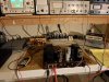
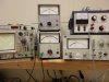
2. All wired up on the test bench for another EKG.

3. The 10 kHz sq wave remains largely unchanged from before.

A bit of a break for now, but at least when I return, some real progress can now be made!

Dave
 

Attachments

  • SA-100 Retest 005.jpg
    SA-100 Retest 005.jpg
    39.9 KB · Views: 208
  • SA-100 Retest 004.jpg
    SA-100 Retest 004.jpg
    92.6 KB · Views: 251
  • SAM_0029.jpg
    SAM_0029.jpg
    89.7 KB · Views: 248
is that a copper plated steel chassis? If so, would there be any gains to soldering the grounding points in addition to the mechanical rivet connection? My Sherwood has soldered and riveted terminal strips, and it just seems like a solid way to make a ground connection.
 
Gadget -- It is definitely not a copper plated chassis, but the chassis does look to have a very high copper content to it.

I agree completely with your approach for the long term -- either that or a buss running between the ground points. Short term -- for now anyway -- using Cramolin and restamping the rivets has nailed the problem cold.

I had put that thought down as something for the owner to do as he might wish. My effort here is simply to get the unit fully and properly operating up to its maximum stock potential, install EFB II in it, and retest. This really wasn't a full restore or rebuild effort. However, the ground issue was significant enough that I felt as it was, it wouldn't allow maximum stock performance, so I took the approach I did. Plus, I really don't have a gun with enough wattage to do that job properly.

On the other hand, the concern I have with that approach is what it would do to the paint on the outside. I'm afraid there is a possibility that it would wrinkle/crinkle it if too much heat is used. One thing is for certain: The chassis was painted, and then the T-strips and rivets were added later -- which may be why Fisher didn't solder them either.

Dave
 
ah, fair point on the paint. I don't have any painted amp chassis so thats never been something I've been concerned about.
 
What i like about both of these threads is the methodical approach dcgillespie uses. Also, the judgement calls about what to do and not to do and why are very illuminating.
 
Progress Update

Today I finished removing all the old bias supply and screen supply components from the original construction to make room for the new EFB II circuits that will control those elements.

I debated for some time as to the best way to approach installing the new circuits, but after removing the old components, it seemed to me that the best way was to use to old terminal point strips plus one new one, as that way would make it easiest for any who may want to duplicate these efforts in their SA-100.

Pics include:

1. The chassis stripped bare of the old bias and screen supply components.

2. In the rear, the old bias and screen components removed (the components on the left are the defective ones that had to be replaced to bring the unit back to its full stock capability), while in the foreground, the original components used to develop EFB II for the SA-100. Thanks to everything learned from the clone build, the component count can be reduced to eliminate the extra controls used in that effort to help determine the best operating point.

Also, look at all those space heater power resistors from the original design that dissipated nearly 18 watts under the hood, compared to the components of EFB II, that collectively dissipate less than 1.5 watts. There are just some things that SS components do better!

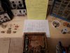
3. Schematic and notes all laid out ready to start installation.

When finished, tested and the performance is documented, then a whole host of other Fisher (and other manufacturers) pentode applications can be evaluated for EFB II, and the common goals of improved performance, cooler operation, and longer tube life sought here.

I hope to get started on the installation later this week.

Back soon.

Dave
 

Attachments

  • SA-100 Ready For EFB II Install 003.jpg
    SA-100 Ready For EFB II Install 003.jpg
    93.4 KB · Views: 382
  • SA-100 Ready For EFB II Install 005.jpg
    SA-100 Ready For EFB II Install 005.jpg
    66.5 KB · Views: 354
  • SA-100 Ready For EFB II Install 004.jpg
    SA-100 Ready For EFB II Install 004.jpg
    81.6 KB · Views: 341
I'm really looking forward to seeing your results with this, since I've got an approximately similar amp I'd like to do this to.
 
Progress

Geez, at this point I feel like I'm reviving my own old thread! I apologize for the delays. There's nothing wrong with the project; life just has a way of injecting its own demands at will. Hopefully, things should move rather rapidly now.

The purpose of this installment is basically to show what the new circuits are comprised of component wise, and basically how simple they are.

But first, it has become apparent (at least to myself), that trying to distinguish between EFB(tm) and EFB II is at the very least confusing, because with the different options that exist to install EFB operation in a variety of different output stage circuits, it became confusing to know just which the heck version was being used. Therefore, in keeping with the all important kiss principle, the designator EFB II has been nixed in favor of simply referring to the various regulator circuits that make up the EFB family of regulators to produce EFB operation. They include:

1. The original EFB cathode regulator: It produces fixed bias operation and EFB action all in a simple one stop one shop package. Use it to add fixed bias operation and EFB action to any circuit, whether to replace a previous resistive cathode bias system, or as an option to chew up some excessive B+ if needed with today's higher line voltages. This is the EFB regulator that was used in the original Dynaco SCA-35 article.

2. The EFB bias supply regulator: It brings EFB action to designs that already employ traditional fixed bias operation from a negative bias supply.

3. The EFB screen regulator: Required in pentode installations of EFB where the screen voltage operates at less than 95% of the plate voltage. In pentode installations where the screens operate at 95% or greater of the plate voltage, this regulator is not required. When used, it is used in conjunction with either the EFB cathode regulator or bias supply regulator above.

With that established then, the progress on the amplifier so far can then be summarized as follows:

1. The amplifier was first repaired and brought back to full performance capabilities , and then its stock performance documented.

2. The amplifier was then prepared for the installation of EFB. This included: (1) Removal of the old bias supply components. (2) Removal of the old screen bleeder regulator components. (3) Removal of the old cathode circuit components. (4) Removal of the antiquated damping control circuits. (5) Installation of individual 100 ohm screen stability resistors at each output tube socket. (6) Installation of individual 10 ohm cathode resistors for each output tube. (7) Connection of each individual output tube cathode terminal to one of the newly freed up terminals on the output terminal strips to allow for proper bias and balance adjustments.

To be fair, items #3, 4, 6 & 7 do not technically need to be done to allow for the installation of EFB in the SA-100. But for Fisher to go to the added effort of providing bias and balancing controls for each channel, only then not to provide facilities to individually measure the current draw of each output tube is just silly. Items #3 & 6 correct this, while items #4 & 7 simply allow for a clean installation of this improvement without any physical changes being made to the chassis. I believe my approach to this portion of the modification has nothing but upside gains, with virtually no one missing the old damping control system.

Which brings us to where I am now. Installation of EFB into the SA-100 now comes down to the installation of 3 rather simple sections:

1. The new bias supply has been installed and tested. Where as the old bias supply only produced about -28 vdc at the output of the bias rectifier, the new circuit produces about -55 vdc.

With the old system, the -28 volt rail was supplied to the bias/balance circuits that ultimately dropped the bias to about -11 vdc at each output tube. Since the "enhanced" portion of EFB is being added to this unit by way of an EFB bias supply regulator (as opposed to the EFB cathode regulator used in my clone), that requires that the voltage at the output of the bias supply be raised (basically doubled). This is to allow for the additional voltage required for the EFB bias supply regulator to operate from, in addition to the bias voltage it needs to send on to the output tubes for proper bias.

2. The EFB bias supply regulator has been prewired and tested to allow for easy installation into the unit. Note that this type of EFB regulator could also use a 3-T regulator as the cathode regulator version does. In fact, my original effort with this regulator some years ago did in fact use a 3-T regulator. But since this type of EFB regulator passes very little current, the use of a 3-T regulator in this case is impractical as it's use would require more current to be drawn through it just to operate itself, than is required by the rest of the whole bias system in total. Therefore, a simple 2 transistor inverter circuit is used between the output of the new bias supply and the input to the old bias balance control circuits. It effectively locks the bias voltage (once set) to the screen voltage so that they both track up and down proportionately together. With the relationship locked, the lowest distortion operating point is always maintained then regardless of how the raw B+ level may fluctuate. These modifications to the bias system cause it to draw no more current than the original design did.

3. Installation of the EFB screen regulator will be the last components to install. Since the screens operate at well below 95% of the plate voltage in the SA-100, an EFB screen regulator is a must with this project. The six components used to make up this EFB regulator will replace all those high wattage screen bleeder resistors of the original design, and allow for significantly cooler operation. Like the EFB bias supply regulator for the control grids, the EFB screen regulator locks the relationship of the screens to the plates proportionately, so that they always remain at the optimum value for the load offered by the OPT.

In this way then, with the relationship of the screens and plates locked into place by the EFB screen regulator, and the relationship of the control grids and screens locked into place by the EFB bias supply regulator, then all the elements of the output tubes will have their voltages remain proportioned together in lockstep with one another regardless of how the basic B+ supply might vary. Yes, because of the design variables that the screens add to the mix with pentode operation (in this case), it is slightly more complicated than that which a simple UL output stage requires. But EFB action is achieved just the same for just a little more work, and should return significant benefits for the SA-100 -- if only to cool this sucker down!!

Pics include:

1. The new bias supply components installed.

2. The prewired EFB bias supply regulator.

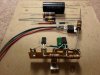
3. The components comprising the EFB screen regulator. Some components are already precut to length in this shot.

4. These components then make up the total of the two EFB regulators necessary to produce EFB operation in the Fisher SA-100.

Next time, it will be all buttoned up with the modification installed, and ready for it's date over on the performance assessment bench.

Dave
 

Attachments

  • SA-100 EFB II Components 004.jpg
    SA-100 EFB II Components 004.jpg
    64.6 KB · Views: 397
  • SA-100 EFB II Components 003.jpg
    SA-100 EFB II Components 003.jpg
    69.3 KB · Views: 367
  • SA-100 EFB II Components 002.jpg
    SA-100 EFB II Components 002.jpg
    43.6 KB · Views: 373
  • SA-100 EFB II Components 001.jpg
    SA-100 EFB II Components 001.jpg
    73.6 KB · Views: 412
Headed Home

The SA-100 is all finished and buttoned up now. The operation of the EFB circuits have been verified, and the bias and DC balance controls initially set to 25 ma quiescent total current draw per tube -- this being the optimum operating point as determined in my clone version of this amplifier. I will now let the amplifier cook for 8 hours to let everything settle in, and then the testing will begin.

The pics provided in this post show how easily the new circuits fit into place where the old screen regulator circuit once resided, and in the open space under the OPTs as well. As Hannibal of the A-Team used to say: I love it when a plan comes together!


Pics here include:

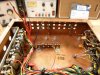
1-2: The EFB screen regulator components all mounted up and soldered into place using the original terminal strips. The Mosfet pass element of this circuit can clearly be seen bolted to the chassis using an insulating mount kit and silicon grease. This mount kit is a must since the tab of this TO-220 device in this design operates at some of the highest B+ levels in the unit.

3. Both of the EFB circuits installed, with the bias supply regulator in the foreground, and the screen regulator in the background.

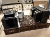
4. An overall shot of the finished work. The owner of the amplifier is not completely certain of this amplifier's future, so I rather intentionally used period NOS components where possible to minimize the altered look of the original build. Bottom line though, is that there was nothing done to the amplifier that cannot be reversed to put the amplifier back to its exact original condition. Therefore, for those familiar with the underside view of these amplifiers as originally produced, the look is altered -- but hopefully, not so much as to draw undo attention to itself.

5. The single exterior give away that something here is different. This screw mounts the power Mosfet of the EFB screen regulator circuit to the inside of the chassis, using one of the original heat ventilation holes. But thanks to the insulating kit, there no shock hazard from touching it at all.

Next time, the performance results will be posted, with a simple explanation of the circuits offered to implement EFB in the SA-100.

Dave
 

Attachments

  • Finished SA-100 with EFB 002.jpg
    Finished SA-100 with EFB 002.jpg
    91.8 KB · Views: 421
  • Finished SA-100 with EFB 003.jpg
    Finished SA-100 with EFB 003.jpg
    75.9 KB · Views: 374
  • Finished SA-100 with EFB 005.jpg
    Finished SA-100 with EFB 005.jpg
    103.6 KB · Views: 384
  • Finished SA-100 with EFB 007.jpg
    Finished SA-100 with EFB 007.jpg
    115.4 KB · Views: 402
  • Finished SA-100 with EFB 001.jpg
    Finished SA-100 with EFB 001.jpg
    39.9 KB · Views: 352
Book 'em Dano!

Today I had a chance to put the EFB modified Fisher SA-100 through its paces. The results were very encouraging.

Recapping the stated goals for this project:

1. A 25% increase in continuous power output per channel with both channels driven, within the power bandwidth of 25 Hz to 20 kHz. This increase would mean that each channel would deliver 20 watts RMS with both channels driven within this power bandwidth.

2. A decrease of mid band (30 Hz to 15 kHz) THD by 50% over that produced by the stock design with both channels driven.

3. A 20% reduction in total quiescent idle current per tube.

4. Notably cooler operation.

The results:

1. With both channels driven, the modified SA-100 will now produce a continuous 20.5 watts RMS per channel (at the onset of clipping), from 25 Hz to 20 kHz. This represents a 28% increase in power output over the original 16 watts per channel produced under these conditions, achieving the goal sought. (Single channel performance now produces nearly 25 watts RMS over this bandwidth)

2. With both channels driven, the modified amplifier now produces .29% THD at 1 kHz at 20 watts RMS power output. This is a 27.5% improvement in distortion over the original .40% recorded under the same conditions with the stock amplifier, but it must be remembered that the figure for the stock amplifier was produced at only 16 watts RMS per channel, because with both channels driven, that was the maximum RMS power that the amplifier could develop.

When the modified amplifier was tested at 1 kHz with both channels driven at 16 watts RMS, the average measured distortion was only .11%, representing over a 70% reduction in distortion.

At 30 Hz and 15 kHz, the results were similar with typically a 20% improvement in distortion readings at the 20 watt level over that produced at the original 15.5 watt level produced in the stock unit at these frequencies. When the modified amplifier was tested at the 15.5 watt level, total distortion was reduced at least 50% at these frequencies, and over the entire specified bandwidth.

To summarize then, while the full power distortion of the modified unit only fell an average of 25% over the full power readings of the stock unit, consideration must be given to the fact that full power of the modified amplifier was at least 25% greater than that of the stock unit. When the modified amplifier was tested at the same power levels that the stock amplifier produced, distortion at all frequencies within the prescribed bandwidth was at least 50% lower, and typically over 60% lower. Based on these facts then, I believe the spirit of the goal has been met.

3. Fisher specified a total current draw of 60 ma per channel of quiescent current for the original design, and I found this particular amplifier to produce minimum distortion with an total quiescent current draw of 31 ma per tube in stock condition, which is very close to the original Fisher specification.

With EFB installed, minimum distortion was now produced at a total quiescent current draw of only 24 ma per tube -- or exactly the same current level found to produce the lowest distortion operating point in the clone amplifier as well. While this reduction in current draw did cause the B+ level to increase somewhat, even with the increased B+, it still reduced output tube plate dissipation from 12 watts per tube to 10 watts. This is a 16% reduction in dissipation per tube, and results in operating the plates at 83% of their Design Center dissipation rating, which is a very conservative point to operate a tube at. That it now also represents the lowest distortion operating point as well? Priceless!! Based on these results then, the stated goals for this area were also met.

4. Cooler operation. Within 15 minutes, the stock unit would almost burn my hands when touching the sides of the unit. Hardly scientific, but factually true. To be perfectly fair, the PT side of the unit does still get notably warm after 15 minutes now, but nowhere near what it used to (it has the dropping resistors coming off the rectifier tube located there), while the OPT side of the amplifier now remains cool now even after some hours of operation. It used to be the hottest side of the amplifier by far.

As I said, there is nothing scientific regarding the measurement of this goal. But consider this: (1) The amplifier now dissipates about 26 less watts of energy electrically (17 of it under the hood), which also means that (2) The power transformer is now delivering at least 26 less watts of energy as well, making it run considerably cooler. The cumulative effect of these changes is quite notable. Overall, the amplifier becomes only reasonably warm now after extended operation (2 hours or more), where as before, this sucker was a fire cracker after that amount of time. Anybody who has one knows what I am talking about. By any stretch of the imagination then, the goal for this area was met as well.

Sonically, the amplifier still retains that wonderful EL84/6BQ5 sound, but takes on the punch capability of a good 7591 amplifier by comparison. Neither the clone nor the SA-100 modified with EFB ever give you that feeling that you're right on the edge of available power during demanding passages, and both handle peaks in stride. In short, it still sounds like an SA-100 -- but with more kick. I produces that effortless sound that I enjoy, with a dynamic capability and clarity that is immediately recognizable.

Pics include:

1. Connecting the finished amp up for testing. Note that the old "Com" and "X" terminals on the output strips are now the current draw test points for the output tubes. With the straps in place, total current draw for a complete channel can be measured as before, while without it, each tube can now be measured individually.

2. The test setup and ready to go.

3. 20.0 watts RMS per channel, both channels driven at 1 kHz, producing .29% THD. Left channel on the top, right on the bottom. This power and distortion level was not available from the stock design.

4. 16.0 watts RMS per channel, both channels driven at 1 kHz, producing only .11% THD. The original amplifier produced .4% THD under the same conditions.

5. 20 watts RMS per channel, both channels driven at 25 Hz. It is hard to photograph this trace due to the slow scan rate required to display a stable single cycle trace at this frequency. The original amplifier could get nowhere close to producing this power level at this frequency with both channels driven. Distortion is about 1.5%, and will be discussed in the Epilog.

In the next and final entry, a sketch of the installed EFB circuit will be provided, as well as a quick discussion of circuit operation, and some final thoughts on other possibilities for the SA-100 amplifier. A general comparison will be made to the clone amplifier as well.

This has been a wonderful and instructive project for me. For the rest of you Fisher Fans, and you 7591 fans in particular, the installation of this type of EFB modification in your integrated amplifiers and receivers is particularly noteworthy. Currently (no pun intended), it is common practice to back off of specified quiescent current levels to aid in tube life and reduce the overall heat generated. But to do so is always done at the expense of performance in the stock designs. Using the combination of EFB regulators shown in this project however will be very appropriate for a great many Fisher products, allowing you to have your performance cake, and extended tube life too.

Epilog to follow soon.

Dave
 

Attachments

  • Finished SA-100 EFB Performance 005.jpg
    Finished SA-100 EFB Performance 005.jpg
    57 KB · Views: 220
  • Finished SA-100 EFB Performance 004.jpg
    Finished SA-100 EFB Performance 004.jpg
    74.1 KB · Views: 193
  • Finished SA-100 EFB Performance 003.jpg
    Finished SA-100 EFB Performance 003.jpg
    77.8 KB · Views: 201
  • Finished SA-100 EFB Performance 001.jpg
    Finished SA-100 EFB Performance 001.jpg
    84 KB · Views: 217
  • Finished SA-100 EFB Performance 002.jpg
    Finished SA-100 EFB Performance 002.jpg
    71.8 KB · Views: 234
Dave,
Outstanding job. You are very inspiring and I really appreciate your attention to the problems of us Fisher folks.

I've been concerned for a while about power consumption and the added expense to the utility bill, which is not negligible, at least where I live. This looks like a true method of addressing that issue directly, and skipping the summer bias phenomenon.

I look forward to being able to implement these changes based on your modifications of the SA-100 schematic and advice about implementation in other circuits. It's likely to be something I'd like to put in all units moving forward.
 
Epilog

With this post, I have provided a schematic of the EFB(tm) modifications installed in the SA-100. I will go over the modifications in a moment, but first, some general comments.

This unit comes from an older generation of Fishers, so any such unit will need to be gone over carefully. I've already documented the ground issue, which should be checked in all units. Also, the general build and small component quality improved in succeeding years, so that aspect of earlier generation equipment should be examined as well. On the other hand, I think the earlier generation's transformers are brawnier, as there are far fewer failures with the earlier models than in the latter years.

The design of the amplifier portion of the SA-100 is certainly good, although could likely benefit from a closer examination of the NFB/stability scheme used. The sq wave performance of the unit was documented previously, and is generally good, but not nearly as good as that of the clone version. Whereas that amplifier displayed a wave form with a very flat top, it also had an extended response to 70 kHz, while the SA-100's response is basically to 1/2 that level, and displayed a sq wave that was somewhat compromised. The stability displayed in both the SA-100 and the clone were absolute.

Another area of opportunity in the SA-100 -- and likely represents the biggest difference between the clone and the EFB modified SA-100, is that of the basic power supply. The power transformer and rectifier are capable enough, but the healthy choke used in the clone version represents a significant advantage in the war on distortion over the power supply of the stock design. While the simple series dropping resistor used in the SA-100 provides filtering enough for normal listening purposes, its limitations show up in the slightly higher distortion levels produced, and particularly so at the lowest frequencies. The level of AC ripple current present under high demand conditions at the OPT CT is significant in the SA-100 (over 10 vac). With the clone, it remains negligible in high demand conditions over the entire audio spectrum, which allows for lower distortion levels to be achieved due to the elimination of this influence.

The problem is space. This little amplifier has no room for the choke I chose for the clone. I then thought of using a smaller choke to supply just the screen and driver circuits, but the EFB screen regulator provides significant filtration by itself, making any gains from this approach nil. To improve filtering any further, it is the filtering for the plates that requires attention. For a choke to be effective under high levels of current draw, it takes size to fill that bill. Still, a small choke could be added in the area under the OPTs which would offer some benefit, as there is a very low level hum attributed to the limited plate filtering used in the original design. A small choke would certainly tamp that hum down, but not offer the distortion reduction benefits at elevated output levels that a full sized choke will provide. But even to install a small choke would require altering the installation of the EFB circuits to allow for the extra space. It could be done, but would be a chore, first requiring the removal of the Channel B OPT to gain access for drilling the mounting holes.

These two areas then represent the biggest difference that exists now between the clone and modified SA-100. Both units sound superb. I do give the edge to the clone version however, as I do believe the approach used in that unit to generate absolute stability allows for a more open sound if not certainly its extended bandwidth. I would again emphasize that both of these amplifiers sound like 6BQ5 amps on steroids. They just have that extra punch enjoyed by the 7591 crowd. Also, the degree to how much cooler the SA-100 operates now cannot be overstated. The reduction in heat output is more than significant -- which is important when cramming so much horsepower into so little space.

With regards to the EFB regulator circuits themselves, the screen regulator is almost a direct copy of the regulator I designed for my clone version, without the voltage adjustment control I used on that version. Its operation is very simple. The output stage in the original SA-100 operates as almost a text book copy of the conditions published by RCA for a 24 watt output level, where in the screens operate at 75% of the plate voltage. While this relationship is established under quiescent conditions in the original SA-100 design, it falls apart as power output increases -- and more so in the SA-100, where an attempt was made to semi-regulate the screens, but not the plate voltage. As power output increases then, the relationship becomes destroyed with only one of these elements regulated, shifting the optimum required load, reducing power, and increasing distortion. Because the EFB screen regulator now holds the proportion of the plate and screen voltages in place, the screens always maintain their optimum 75% operating potential with regards to the plate voltage -- whatever that voltage falls to, and regardless of any increase in screen current due to increasing power output. The result is that the load line of the output stage remains largely in tact even though the main supply is unregulated, and actually drops by nearly 100 volts from 0 to full power output in both channels! The EFB screen regulator is largely responsible for the 25%+ increase in power output available from the modified amplifier.

The small .47 uf cap helps to provide significant filtering so that ripple applied to the screens is in the millivolt region, yet it is small enough to allow the regulator circuit to react quickly with any changes in plate voltage.

As detailed in the clone thread, the Mosfet device is quite over-rated for the job it does being a 500 volt device, and capable of passing some 9 Amps of current. It should last a lifetime.

The EFB bias supply regulator is newest EFB regulator to be published, and consists of a simple two transistor inverter circuit, supplied from a modified version of the original bias supply, and controlled by the screen voltage supplied by the screen regulator.

In a pentode, the screen voltage sets the maximum current that can flow at any given instant, so control of it is important to maintain the load line as discussed above. But if the screen voltage moves at all, then the bias voltage needs to move proportionately as well, or the original low distortion operating point set under quiescent conditions is destroyed, once again causing elevated distortion with increasing power output. Therefore, as the screen voltage changes, so must the bias voltage.

In the SCA-35 EFB installation, the cathode regulator provided fixed bias and adjusted the set point all in one neat package. But in the SA-100, fixed bias is already part of the design. Therefore, in this case it is more appropriate to control the bias supply itself with an EFB bias supply regulator.

In the schematic, the left transistor provides the inversion -- causing a negative bias voltage to go more positive, as a positive screen voltage goes more negative at the screen. The right transistor isolates the load of the standard DC bias and balance controls used so that their setting does not interact with the inverter stage's operation.

The original components R56, M1, C2, and R51 in the bias supply (Sams designations) have been adjusted to provide more bias voltage for the bias supply regulator to operate from. That, together with the installation of the bias supply regulator, cause the actual control settings of the bias and balance controls to change very little from that of the original design -- given the same output tubes in the same socket locations.

As in the clone amplifier, both EFB regulators in the SA-100 come together to produce a superb result. It is common for most manufacturers who set up their output stages to mirror published conditions, to do so with one exception: they increase the quiescent current significantly (when possible) to account for the power supply droop that exists as power output is increased. Fisher did as much in the SA-100, by specifying a quiescent current draw that ran the dissipation levels right up to the limits of the tubes -- the idea being that as voltage levels fell with increased power output, the output stage would then "fall" into the low distortion operating point established by RCA to maintain performance under conditions of high power output. Without any other means of economically regulating the potentials of the tubes, it was really the only means they had at their disposal. Today, enter EFB.

Because the EFB bias supply regulator reduces the bias voltage as screen voltage drops, the bias voltage can then be set for the true low distortion operating point under quiescent conditons, and the supply regulator will then maintain that operating point as the screen voltage falls with increasing power output. In this case, it allowed low distortion set point to be reduced from 31 ma for the stock design, to 24 ma for the EFB modified design. This allowed a significant 15%+ drop in output tube dissipation, resulting in extended tube life, and cooler operation.

Well, that's about that. With three different EFB installations now documented, and between them, all three of the different EFB regulators employed, I can finally turn my attention to my next article on EFB, wherein I will discuss when and where the various regulators are most appropriate to use. A break for the holidays before starting that article (to be published on Tronola), but with the book closed on the clone and SA-100 EFB projects now, I hope to start that effort sometime in December, time permitting.

With three regulators in the EFB family now, there is virtually no application that cannot use EFB to good advantage. Happy listening!

Dave

 

Attachments

  • 001.jpg
    001.jpg
    43.1 KB · Views: 607
  • 003.jpg
    003.jpg
    92.9 KB · Views: 424
Very sweet indeed. I'd love to see what this mod could do with my Sherwood but frankly I don't know that there is room to put anything else in there. I also don't own measuring equipment to actually get numbers anyway.
 
Well, that's about that. With three different EFB installations now documented, and between them, all three of the different EFB regulators employed, I can finally turn my attention to my next article on EFB, wherein I will discuss when and where the various regulators are most appropriate to use. A break for the holidays before starting that article (to be published on Tronola), but with the book closed on the clone and SA-100 EFB projects now, I hope to start that effort sometime in December, time permitting.

With three regulators in the EFB family now, there is virtually no application that cannot use EFB to good advantage. Happy listening!

Dave

Now I wanna EFB my Fisher 660-A and my Phisher 30-A clone(s)! See what you made me do!?!

-D
 
I see this as perhaps the most significant 'advancement' in Tube Amplification Design to come along since outputs went Ultra-linear! I'm utterly amazed at how much sense this whole thing makes as I read through it.....and maybe even equally amazed that I was actually able to follow 'most' of it. Dave....your write-ups really are an epiphany!

I'll be in touch! In Michigan for the week........

Thanks Mr. Gillespie!

Tom D.
 
Thanks Tom -- UL and EFB are similar in that both concepts work to fundamentally alter (or adjust) the operation of the output tubes. But whereas the UL connection alters the operation of the output tubes according to the actual load reflected back to them at any given point in time, EFB action adjusts the output tubes according to the actual power supply conditions presented to them at any given point in time. Both concepts act to increase power and reduce distortion, because they both work to maintain an optimum operating point for the tubes, based to the real conditions that actually exist in time.

That being said however, I am hardly angling to rise to the lofty heights of misters Hafler and Keroes!

Dave
 
Last edited:
Dave, if this EFB I, II & III stuff catches on......your 'ascension' may be pre-ordained.
 
Last edited:
Back
Top Bottom