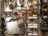
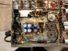
Here we go again, looking to make the most of a very good Fisher amplifier, by (1) Capitalizing on any significant compromises in the original design, and (2) better adapting it to today's audio environment.
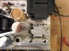
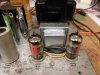
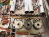
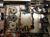
This time, it's the X-101C, in the form of Audiodon's ratrig. Currently, it has been brought up to original performance specifications as documented in his thread:
http://www.audiokarma.org/forums/showthread.php?t=491521&page=7
and is now undergoing listening tests while the project is contemplated.
In our various conversations, Don has expressed to significant concerns with the unit, that include:
1. It tends to run out of gas in the power output department, as compared to other similarly tubed Fisher units, and
2. The heater string cathode bias system used in this design limits any relaxing of output tube quiescent current to help accommodate newer tubes or extended tube life in general: If you reduce it much at all, the heaters in the small signal tubes won't come up to temp, so the unit won't work.
Both of these issues are related, so fixing the bias system can potentially yield a twofer in results. He has also asked that some of the improvements I made to his Fisher X-1000 be considered for this project as well. They include:
1. A tone control bypass option, and
2. Modifying the near useless Reverb Input/Output jacks into much more useful Preamp Output/Power Amp Input jacks.
To this, I added dumping the powered center channel output, and converting the main L and R outputs so that the Common output connection is in fact at ground level, rather than floating above ground as found in the original design.
This third modification has three distinct advantages:
1. It makes testing of the unit painless and much more effective with test equipment having dual inputs with a common ground (such as scopes), or equipment that includes a common ground path through the AC line ground system. Since testing/measuring is an area that Don is is pursuing, this will ease his effort into this new area for him.
2. It allows the use of external speaker switching systems or circuits that require a common ground output.
3. In the case of the X-101C, it will also make the unit correct with regard to absolute phase. As originally designed, the X-101C reverses phase for all inputs except that heard through the Tape Monitor setting.
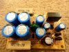
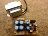
The elephant in the middle of the room with this project, is that if the small signal tube heaters are no longer to be powered by output tube current draw, then an alternate source (power supply) is a must. While this will in fact involve some slight alterations to the X-101C's chassis to accomplish this, addressing this issue is very much more than worth the effort, as testing has shown that the original bias system used represents a HUGE compromise to this Fisher. In fact, the compromises are virtually identical to those I addressed in my original article on EFB(tm), so for those interested in this project, a review of that article would be of benefit in understanding why the compromise is so significant. In that article, you can virtually substitute "Fisher X-101C" for "Dynaco SCA35", and the article will still be 100% accurate with regards to the problems discussed regarding the original design, and the results produced when modifying the unit with EFB. In fact, the results that EFB can produce in the X-101C is even more significant than that achieved in the SCA/ST35 amplifiers, because the performance deterioration that occurs with both channels driven in the X-101C is even greater than that which occurred in the small Dynaco amplifiers. The original article on the introduction of EFB can be found here:
http://www.tronola.com/A_New_Look_At_An_Old_Friend.pdf
Finally, it should also be noted that the Fisher X-101C is for all intents and purposes (except for the bias system employed), the audio section of a Fisher 400 receiver. IN PARTICULAR, specifically that of an EARLY version 400 receiver, as along with the same basic topology, even though they have different part numbers, the output transformers in this unit measure EXACTLY the same electrically and physically as that of a bonafide early version Fisher 400 OPT that Don had sent me for testing last year. So, owners of the early version 400 receiver just might want to follow along with this project as well.
So, there's the project. More as it begins to unfold!
Dave
This time, it's the X-101C, in the form of Audiodon's ratrig. Currently, it has been brought up to original performance specifications as documented in his thread:
http://www.audiokarma.org/forums/showthread.php?t=491521&page=7
and is now undergoing listening tests while the project is contemplated.
In our various conversations, Don has expressed to significant concerns with the unit, that include:
1. It tends to run out of gas in the power output department, as compared to other similarly tubed Fisher units, and
2. The heater string cathode bias system used in this design limits any relaxing of output tube quiescent current to help accommodate newer tubes or extended tube life in general: If you reduce it much at all, the heaters in the small signal tubes won't come up to temp, so the unit won't work.
Both of these issues are related, so fixing the bias system can potentially yield a twofer in results. He has also asked that some of the improvements I made to his Fisher X-1000 be considered for this project as well. They include:
1. A tone control bypass option, and
2. Modifying the near useless Reverb Input/Output jacks into much more useful Preamp Output/Power Amp Input jacks.
To this, I added dumping the powered center channel output, and converting the main L and R outputs so that the Common output connection is in fact at ground level, rather than floating above ground as found in the original design.
This third modification has three distinct advantages:
1. It makes testing of the unit painless and much more effective with test equipment having dual inputs with a common ground (such as scopes), or equipment that includes a common ground path through the AC line ground system. Since testing/measuring is an area that Don is is pursuing, this will ease his effort into this new area for him.
2. It allows the use of external speaker switching systems or circuits that require a common ground output.
3. In the case of the X-101C, it will also make the unit correct with regard to absolute phase. As originally designed, the X-101C reverses phase for all inputs except that heard through the Tape Monitor setting.
The elephant in the middle of the room with this project, is that if the small signal tube heaters are no longer to be powered by output tube current draw, then an alternate source (power supply) is a must. While this will in fact involve some slight alterations to the X-101C's chassis to accomplish this, addressing this issue is very much more than worth the effort, as testing has shown that the original bias system used represents a HUGE compromise to this Fisher. In fact, the compromises are virtually identical to those I addressed in my original article on EFB(tm), so for those interested in this project, a review of that article would be of benefit in understanding why the compromise is so significant. In that article, you can virtually substitute "Fisher X-101C" for "Dynaco SCA35", and the article will still be 100% accurate with regards to the problems discussed regarding the original design, and the results produced when modifying the unit with EFB. In fact, the results that EFB can produce in the X-101C is even more significant than that achieved in the SCA/ST35 amplifiers, because the performance deterioration that occurs with both channels driven in the X-101C is even greater than that which occurred in the small Dynaco amplifiers. The original article on the introduction of EFB can be found here:
http://www.tronola.com/A_New_Look_At_An_Old_Friend.pdf
Finally, it should also be noted that the Fisher X-101C is for all intents and purposes (except for the bias system employed), the audio section of a Fisher 400 receiver. IN PARTICULAR, specifically that of an EARLY version 400 receiver, as along with the same basic topology, even though they have different part numbers, the output transformers in this unit measure EXACTLY the same electrically and physically as that of a bonafide early version Fisher 400 OPT that Don had sent me for testing last year. So, owners of the early version 400 receiver just might want to follow along with this project as well.
So, there's the project. More as it begins to unfold!
Dave