Tone Control Bypass and Filter Removal
Engineering is often a game of dominoes, wherein you have to do this because of that, which means you have to do something else because of this, which means you have to...... You get the idea. In the X-101C, the original "that" of this conversation begins with the output stage: The biasing and loading conditions employed in this stage required substantially more NFB to be used in the power amplifier section (the "this") to achieve similar performance levels, as the otherwise almost identical fixed bias version of this power amplifier section as used in so many of the Fisher stereo receivers.
Continuing on, this expedient then required more gain from the line/tone amplifier stages to achieve a reasonable input sensitivity, in keeping with other Fisher products. The extra gain was found by eliminating the negative voltage feedback typically placed around the tone amplifier stage (which immediately precedes the power amplifier section), as used in virtually all other examples of this overall design. Even at that, the X-101C still has a somewhat greater input signal requirement (less sensitivity) than its many brother, sister, and cousin designs.
This last expedient then is what (in part) caused so much of the rolled off response as documented in post 17, and leads to the challenge of this final modification: Remove the fixed filter circuits, flatten and extend the response of the line and tone stage amplifiers, and do it without the aid of any negative voltage feedback for the tone amplifier stage. To punctuate just how poor the response of this stage is, review pic #2 of post 17, where in the test signal is applied directly to the tone stack and following tone amplifier stage, via the tape monitor input. At this point, response is down nearly 3 db at 20 kHz in the stock design (and even more at reduced volume control settings).
You might recall that Fisher's approach to this problem was to make the preceding line amplifier stage have a rising response to help compensate for the reduced response of the tone amplifier stage. This works after a fashion, but also makes the signal provided at the Recording Output jack have a rising response characteristic versus frequency, since that jack is tapped into the circuit immediately after the line amplifier stage. It also makes for poor performance from any source played through the tape monitor input, since those signals don't pass through the line amplifier stage. Finally, due to the tolerances in the various components used to shape the rising response of the line stage, it can also lead to a dis-similar response between the two channels, as pics #3 and #4 of post 17 show. With the volume control at more normal operating levels, pic #5 then is what you received from this approach.
Adding a tone control bypass feature then represented an opportunity to address the concerns noted above (in addition to adding a simple switch), to make the performance of the preamplifier/control section come up to speed with the improved response of the new power amplifier section. In doing this, advantage was taken of the negative current feedback generated across the unbypassed cathode resistors of the line and tone amplifier stages, along with the usual bypass cap placed across the input resistor of the line amplifier stage. By installing appropriately small value bypass capacitors across these resistors, the response at the Recording Output jack is now very flat to 20 kHz (+0/-.1 db), and through the complete preamplifier/control section, now down only .2 db at 20 kHz with the tone controls disengaged. In fact, overall response from the line level inputs, through the complete preamplifier/control section and power amplifier section to speaker outputs is now +0/- .25 db at 20 kHz at any volume control setting. This is a major improvement over that of the original design, where response at normal volume settings approached -2.5 db at 20 kHz in this same scenario.
With the tone controls engaged, the response of the complete preamplifier/control section is now only somewhat better than it was before, as the response is now primarily a product of the actual tone controls. Even though the response of the tone amplifier stage is now much improved, the rising response of the line amplifier stage before it has been eliminated, thus canceling out a significant portion of the response improvements made to the tone amplifier stage. Therefore, the response is almost entirely driven by the tone controls themselves, with the complete preamplifier/control section producing an overall response of +0/-1.5 db @ 20 kHz at any volume setting with the tone controls engaged.
An opportunity was also taken to help flatten the response of the tone control networks, within the bandpass of their flat setting characteristic. This helped to achieve the the overall response mentioned in the previous paragraph. It also produced a slight inequity in volume level (about 1 db) as the new tone control engage/disengage switch is activated, with a the gain advantage being in the disengaged position. While this could have been leveled out more closely, it would have required more components to achieve non-production component values in an already space challenged chassis. The slight difference in volume level between the two settings from using standard bypass position component values cannot hide the obvious improvements made by removing the tone controls from the signal path.
In all then, the improvements made to the preamplifier/control section are as significant as those made to the power amplifier section, both from a measured and sonic presentation standpoint. The only downside to any of this (if loss of of the original Hi Filter switch feature is in fact a loss), is that shorting plugs now need to be installed in the Tape Head input jacks IF the Tape Head EQ position is selected, and no Tape Head source is plugged in. In that scenario (and only that scenario), due to the HF characteristics of the Tape Head EQ curve, the amplifier will now oscillate with an unterminated input, due to the extended HF response all of the circuits ahead of it now achieve. This is one of the limiting factors in trying to pack so much performance into so little space. The current improvements represent the realistic limits of what the existing physical layout can support. Additional shielding could be installed, but then that can create its own problems as well. The concern is completely eliminated with the use of shorting plugs, or by simply leaving the EQ switch in the Phono position, which is what I'm sure Don will likely do.
Since the likelihood of ever using the Tape Head EQ setting is beyond remote, the problem could also likely be eradicated completely by moving the discrete phono EQ networks installed previously over to the phono preamp tubes, and permanently install them there. This would eliminate the wiring to the EQ switch (and the Tape Head EQ option), but still allow the Tape Head input jacks to serve as inputs for a second TT. Don?
Pics include:
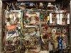
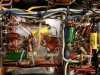
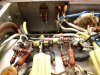
1. The modified line/tone amp stages. Even though some new components are in place, the reworked circuits presents a less cluttered look.
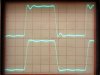
2. A 10 kHz sq wave passing though the complete control section with the tone controls engaged. Circuit response is down 1.5 db at 20 kHz.
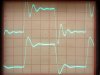
3. A 10 kHz sq wave passing through the complete control section with the tone controls disengaged. Circuit response is down just 0.2 db at 20 kHz.
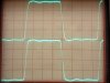
4. Here is an extremely tough waveform to reproduce accurately. This is a 2 kHz sq wave, first passing through a reverse RIAA network, driving the phono preamp inputs, with the tone controls disengaged, and the scope connected to the Preamp Output jack. The quality of this waveform shows the extreme accuracy of the phono, line, and tone stages now. And who says the Fisher phono preamp circuit isn't accurate? These traces were produced using 5751 tubes in the phono preamp positions. For best LF RIAA accuracy, you should always use 12AX7 tubes in these positions.
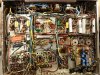
5. Full bottom view of the modified amplifier with all modifications complete.
With the new preamp Output Jacks, it is so nice now to be able to just yank the output tubes, and work on the preamp/control section without the unit producing any heat to speak of. Thanks to the new heater supply, the output tubes are no longer needed to heat the small signal tubes, so the unit can be operated permanently that way as a quality preamp/control center if desired.
I should also point out that unlike the Fisher receivers, the line/tone amp stages are both contained within the same tube for each channel in the X-101C. However, because no loop NFB is used for the tone amplifier stage, channel balance can be affected by the match between these two tubes, although the effect of any routine mismatch is very slight.
Time to clean up the lab, hook up the ratrig for some extended listening tests, and post the final Summary. What a ride this one has been!
Dave